TM-9-2350-311-34-2 - Page 354 of 552
TM 9-2350-311-34-2
6-18
CONTROL ASSEMBLY - CONTINUED
c. Assembly
NOTE
Coat sleeves and slide assemblies and preformed packings with hydraulic fluid before assembling.
Install preformed packings without distorting them. Avoid contaminating finished surfaces.
1
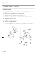
Install seven new preformed packings (50) on traversing sleeve and slide assembly (42).
2
Install two new preformed packings (49) on traversing sleeve and slide assembly (42).
3
Install seven new preformed packings (48) on elevating sleeve and slide assembly (44).
4
Install two new preformed packings (47) on elevating sleeve and slide assembly (44).
5
Apply sealing compound to new plug (45). Install new preformed packing (46) plug (45) and elevating
sleeve and slide assembly (44).
6
Insert traversing sleeve and slide assembly (42) into front end of body (43).
Retaining rings and retainers hold small helical compression springs. Restrain retainer as retaining
ring is installed to avoid injury.
7
Install two new retaining rings (41), two helical compression seats (40) two helical compression springs
(39), two flat washers (38), and two new retaining rings (37).
8
Install two helical compression springs (35) and support (36).
Restrain gunner’s control cover while installing cap screws to avoid injury. Gunner’s control cover
holds two helical compression springs.
9
Install gunner’s control cover (34), four new lockwashers (33) and four cap screws (32).
10
Install flat washer (31), plate (30) three new lockwashers (29), and three cap screws (28) on control valve
body assembly (6).
11
Install two guides (27) on cover plate (26).
12
Install cover plate (26), five new lockwashers (25), and five cap screws (24). Torque cap screws to 30-35
in-lb (3-4 N•m).
6-90 Change 2
Back to Top


