TM-9-2350-311-34-2 - Page 472 of 552
TM 9-2350-311-34-2
14-3 ACTUATOR ASSEMBLY — CONTINUED
c. Assembly
—
Continued
10
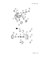
Backlash between gears should be 0.004 to 0.006 inch (0.10 to 0.15 mm). Determine shim(s) (17) required
by adding dimension D etched on access cover (11) to dimension X etched on gearshaft (12) and subtract-
ing dimension E etched on actuator housing (18) from sum ((D + X) - E = Required shims). Install required
shim(s).
PART NUMBER
SHIM THICKNESS
10895666
0.001 inch (0.03 mm)
10895667
0.002 inch (0.05 mm)
10895668
0.005 inch (0.13 mm)
11
Install gearshaft assembly (8) in actuator housing (18) ensuring arrows (15) on gearshaft (12) and bevel
gearshaft (16) match.
12
Install six cap screws (10) and new lockwire (9).
14-12
Change 2
Back to Top


