TM-9-2350-311-34-2 - Page 469 of 552
TM 9-2350-311-34-2
c. Assembly
1
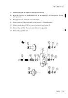
To determine dimension A for shim(s) (25), assemble thrust washer bearing (24) to bevel gearshaft (16).
Measure dimension G and add to dimension XX (etched on bevel gearshaft). Subtract sum of G and XX
from F (smaller dimension etched on actuator housing (18)). Formula is as follows: F - (G + XX) = dimen-
sion A, which is the required shim thickness.
2
Install required shim(s) (25) between sleeve bearing (26) and bevel gearshaft (16) with thrust washer bear-
ing (24) and sleeve bearing (23) attached and insert into actuator housing (18).
3
Assemble sleeve bearing (26), shim(s) (25), thrust washer bearing (24), bevel gearshaft (16), sleeve bearing
(23), and actuator cover (21) in actuator housing (18) to determine shim(s) (22) needed for dimension B.
NOTE
Make sure all components are seated firmly against each other.
4
Using feeler gage, measure distance B at several points around actuator cover (21). Measurement should
not vary. Install shim(s) (22) between actuator housing (18) and actuator cover (21) to ensure fit equal to
dimension B plus 0.002 to 0.004 inch (0.05 to 0.10 mm).
PART NUMBER
SHIM THICKNESS
10895660
0.001 inch (0.03 mm)
10895661
0.002 inch (0.05 mm)
10895662
0.005 inch (0.13 mm)
Change 2
14-9
Back to Top


