TM-9-2350-311-34-2 - Page 459 of 552
TM 9-2350-311-34-2
d. Installation
1
2
3
4
5
6
7
8
9
10
11
Level the gun trunnions using the plumbline method (TM 9-2350-311-10).
Ensure testing and scribing has been performed of the M145/M145A1 telescope mount
(TM 9-2350-311-10).
Boresight the howitzer using the test target method of boresighting with the M118A2/M118A3 elbow tele-
scope (TM 9-2350-311-10).
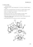
Secure M140 alinement device mount (4) to bracket (3) using two new lockwashers (8) and two cap screws
(7).
Install woodruff key (6).
Secure bracket (3) to mount (5) using two new lockwashers (2) and two cap screws (1). Bracket and M140
alinement device mount (4) should be in line with M42 periscope.
Install M140 alinement device (TM 9-2350-311-10).
With an observer viewing through M118A2/M118A3 elbow telescope, aline bracket (3) and M140 alinement
device mount (4) until the reticle of the M140 alinement device is in coincidence with boresight cross of
M118A2/M118A3 elbow telescope reticle as shown, by loosening and tightening mounting cap screws (7
and 1). Torque cap screws to 45-50 lb-ft (61-68 N·m) when alinement of reticles is met.
Remove Ml 40 alinement device (TM 9-2350-311-10).
NOTE
Drill and ream holes for four headless straight pins if M140 alinement device is new.
If removed, install two headless straight pins (10) in bracket (3) and two headless straight pins (9) in M140
alinement device mount (4).
Install M140 alinement device (TM 9-2350-311-10) and recheck coincidence of reticles which must be
within 0.25 mils.
Change 2
14-4.1
Back to Top


