TM-9-2350-311-34-2 - Page 450 of 552
TM 9-2350-311-34-2
PANORAMIC TELESCOPE BALLISTIC COVER
This task covers:
a. Disassembly
b. Inspection and Repair
c. Assembly
INITIAL SETUP
Tools
Self-locking screws (12) (item 100, Appx E)
Artillery and turret mechanic’s tool kit
(SC 5180-95-CL-A12)
Personnel Required
2
Materials/Parts
Headless grooved pins (2) (item 89, Appx E)
Equipment Condition
Sealing compound (item 30, Appx B)
Panoramic telescope ballistic cover removed
Seals (2) (item 169, Appx E)
(TM 9-2350-311–20-2)
a. Disassembly
1
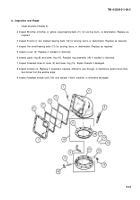
Remove 12 self-locking screws (1), optical holder (2), two seals (3), and window (4) from cover (5). Discard
self-locking screws and seals.
2 Remove two webbing straps (6).
3 Remove eight cap screws (7).
Cover is heavy and requires help of an assistant for removal to avoid injury.
NOTE
When cover is removed, upper ring maybe stuck in it, freeing bearing balls.
4 Remove cover (5).
NOTE
Retain shims unless new components are to be installed.
5 Remove upper ring (8) and shim(s) (9), if used, from lower ring (10).
6 Remove 58 white, off-white, or yellow, large bearing balls (11), 54 pink or red, medium bearing balls (12),
and five small bearing balls (13).
7 Remove two headless grooved pins (14), two rod end clevis assemblies (15), two brake shoes (16), and two
bolts (17). Discard headless grooved pins.
8 Remove two headless straight pins (18) from upper ring (8).
13-2
Back to Top


