TM-9-2350-311-34-2 - Page 458 of 552
TM 9-2350-311-34-2
14-2
M140 ALINEMENT DEVICE MOUNT AND BRACKET (DIRECT FIRE) —
CONTINUED
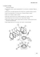
b. Disassembly
1
Remove two cap screws (11), two lockwashers (12), two flat washers (13), and dovetail door wedge (14)
from base (15). Discard lockwashers.
2
Only if necessary for replacement, remove two headless straight pins (16).
c. Assembly
1
Secure dovetail door wedge (14) to base (15) using two flat washers (13), two new lo&washers (12), and
two cap screws (11).
NOTE
Drill and ream holes for headless straight pins if M140 alinement device is new,
2
Drill two holes 0.2495 ± 0.0005 inches diameter.
3
Install two headless straight pins (16), if removed.
14-4
Change 2
Back to Top


