TM-9-2350-311-34-2 - Page 452 of 552
TM 9-2350-311-34-2
PANORAMIC TELESCOPE BALLISTIC COVER - CONTINUED
c. Assembly
1
2
3
4
5
6
7
8
9
10
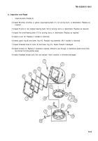
Install two headless straight pins (18) in upper ring (8).
Install two bolts (17), two brake shoes (16), two rod end clevis assemblies (15), and two new headless
grooved pins (14) in lower ring (10).
Place upper ring (8) and shim(s) (9) on lower ring (10). Make sure two headless straight pins (18) are en-
gaged in holes of lower ring and holes in shim(s) are alined with holes in lower ring and upper ring.
Position cover (5) on lower ring (10).
NOTE
Bearing balls are to be arranged in five groups. Follow illustration as a guide when installing bearing
balls.
Raise upper ring (8) from lower ring (10). Insert 58 white, off-white, or yellow, large bearing balls (11), 54
pink or red, medium bearing balls (12), and five small bearing balls (13) into groove formed by lower ring
(10), upper ring (8), and cover (5).
Secure lower ring (10), shim(s) (9), and upper ring (8) to cover (5) using eight cap screws (7). Torque cap
screws to 34-42 lb-ft (46-57 N·m).
Install two webbing straps (6).
Rotate cover (5) to check operation. If cover binds, add or remove new shim(s) (9) as required to obtain
smooth rotation.
Install two new seals (3) and window (4). Small plate of window must face inside cover (5) and etched trade-
mark or number on glass must face outward.
Apply sealing compound to edges of optical holder (2) which meets cover (5). Install optical holder and 12
new self-locking screws (1). Torque self-locking screws to 7-8 Ib-ft (9-11 N·m).
13-4
Back to Top


