TM-9-2350-358-BD - Page 229 of 343
TM 9-2350-358-BD
11-11. HYDRAULIC TUBE AND HOSE REPAIR (HIGH PRESSURE) - CONTINUED
Materials/Tools:
•
Fitting, hose, elbow, 45 degree, 1/4, 3/8, 1/2, 3/4-inch determined by size (item 13, 14, 15, 16, Appendix C)
•
Fitting, hose, elbow, 90 degree, 1/4, 3/8, 5/8, 3/4-inch determined by size (item 17, 18, 19, 20, Appendix C)
•
Fitting, hose, straight, 1/4, 3/8, 1/2, 5/8, 3/4-inch determined by size (item 21, 22, 23, 24, 25, Appendix C)
•
Fitting, hose, socket, 1/4, 3/8, 1/2, 5/8, 3/4-inch determined by size (item 26, 27, 28, 29, 30, Appendix C)
•
Packing, preformed, kit (item 45, Appendix C)
•
Heavy lubrication oil (scavenge from available source)
•
High pressure hose (scavenge from available source)
•
Hydraulic fluid (item 36, Appendix C)
•
Hacksaw or knife (found in M2/3 generic BDR kit, Section III, Appendix C)
References:
TM 9-2350-314-20-2-2
Procedural Steps:
1.
Determine ORS fitting required.
2.
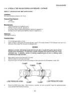
Using unserviceable hose as template for size and length and cut new hose as required.
3.
Clean out inside bore of hose.
4.
Place hose end of fitting socket next to end of hose and measure from end of hose to notch on socket and mark
hose.
5.
Cut hose cover down to the wire reinforcement from measurement done in step 4 to end of hose.
6.
Insert hose into socket using a back and forth rocking and clock-wise motion until hose bottoms out in socket, or
alternate method is to screw socket onto the hose in a counterclockwise motion until it bottoms out.
11-11
Back to Top


