TM-9-2520-234-35 - Page 154 of 323
CHA P
142.
5,
SEC
XV I
Section
DESCRIPTION
RIGHT OUTPUT REBUIL D
PAR
142-143
XVI. RIGHT-OUTPUT SUBASSEMBLY—REBUIL D
Refer to par. 16 for description of the
right-output subassembly.
143. DISASSEMBLY (fig. 381, fold-out 10)
a . Using hoist and sling 8351496, remove
the right-steer planetary carrier and brake
hub assembly (fig. 157). Refer to pars. 157
through 161 for rebuild of the steer planetary
carrier and brake hub assembly.
Note . If carrier and brake hub as-
sembly cannot be removed easily ,
block up under the end of the carrier
shaft, and strike the brake anchor
ring to free the assembly.
b . Remove the right brake plates an d
disks (fig. 157).
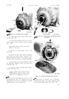
Figure 157. Removing (or installing) right-steer
planetary carrier and brake hub assembly
12 2
Figure 158. Removing (or installing) clutch reaction
plate assembly
c . Remove 18 bolts (two different lengths),
using a 5/8-inch wrench, retaining the brake
anchor ring (fig. 157).
d . Remove brake anchor ring (fig. 157).
Note . Refer to pars. 162 through 166
for rebuild of the right-brake anchor
ring assembly.
e . Using sling 7083778 and three 7/16-
14 bolts, remove the clutch reaction plate as-
sembly (fig. 158). Mark the plate and end
cover for reference at reassembly.
f.
Remove
nine
steer
c1utch
release
springs (fig. 158).
g . Remove two bolts from the outpu t
clutch assembly (fig. 158).
h . Using sling 7083778 and two 5/16-24
bolts, remove the output clutch assembl y
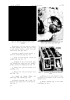
(fig. 159).
Note . Refer to pars. 167 through 171
for rebuild of output clutch assembly.
Back to Top


