TM-9-2520-234-35 - Page 157 of 323
PAR
14 6
RIGHT OUTPUT REBUIL D
CHAP
5,
SEC
xV I
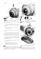
1. Using sling 7083778 and two 5/16-2 4
bolts, install the output clutch assembly (fig .
166). Remove sling and lifting bolts and in -
stall the two remaining 5/16-24 x 5/8 outpu t
clutch assembly bolts (fig. 167). Tighten th e
bolts to 14-18 pound-feet torque and bend cor-
ners of the lock strips against them .
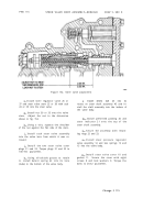
Figure 164. Installing guide bolt used to aline geared
steer clutch and brake components
Figure 165. Installing steer clutch anchor
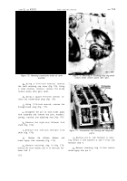
m. Install six internal- and seven ex -
ternal splined steer clutch disks and plates ,
beginning with an external-splined clutch plate
(fig. 167) .
Figure 166. Installing output clutch assembly
Figure 167. Installing steer clutch plates
12 5
Back to Top


