TM-9-2520-234-35 - Page 155 of 323
*C2
PAR
14 3
RIGHT OUTPUT REBUIL D
CHAP
5,
SEC
XV I
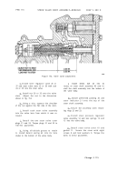
Figure 159. Removing (or installing) output clutch
assembly
i . Remove steer clutch plates and disks
(fig. 159).
j . Remove spacer (fig. 159).
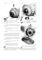
k . Using sling 7083778 and three 7/16-
14 bolts, remove steer clutch anchor (fig. 160).
l . Remove steer clutch piston (fig. 160).
Note . Refer to pars. 172 through 176
for rebuild of the steer clutch piston
assembly .
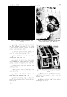
m . Using 5/8-inch wrench, remove 1 9
bolts and lock washers that retain the end
cover hub (fig. 161).
n . Remove the hub and gasket from the
end cover (fig. 161).
o . Remove two preformed packings from
the hub (fig. 161).
p . Remove retaining ring 71 (fig. 381,
fold-out 10) that retains bearing 72 in hub 73.
q . Remove bearing 72 from hub 73.
Figure 160. Removing steer clutch anchor
Figure 161. Removing end cover hub
r . Do not remove the oil seal from the
hub, unless replacement is necessary (fig .
161). If necessary, drive the oil seal out to-
ward the outside of the hub.
s . Using a 9/16-inch wrench, remov e
eight self-locking bolts 62 (fig. 381, fold-out
10) that retain sleeve 61. Remove sleeve 61,
gasket 60 and preformed packing 59.
t . Remove the bearing 70 from sleeve 61.
u. The various plugs may be remove d
from the end cover to aid in cleaning and in-
spection of oil passages (fig. 161).
12 3
Back to Top


