TM-9-2520-234-35 - Page 166 of 323
*C2
*C2
*C2
*C2
*C2
CHAP
5,
SEC
XVII I
REAR
HOUSlNG
REBUILD
PAR
153-156
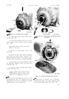
Figure 188. Removing output driven gear
retain the right- and left-brake apply cam
stationary rings (fig. 189).
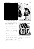
at . Remove left-brake apply cam station-
ary ring (fig. 190). Do not remove ring seal
and expander from ring unless replacement is
necessary .
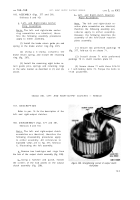
au . Remove right-brake apply cam sta-
tionary ring (fig. 191). Do not remove ring
seal and expander from ring, unless replace-
ment is necessary.
av . No further disassembly of the rear
transmission housing is necessary. If neces-
sary, the various plugs in the housing may be
removed to aid in cleaning the housing .
154. CLEANIN G
Refer to par. 71 for cleaning recommen-
dations.
155. INSPECTION AND REPAIR
Refer to par. 72 for general inspection
and repair recommendations. Repair and re-
build points of measurement for fits, clear-
ances and wear limits are indicated by small,
lower case letters in figs. 377, 378, 379 and
380, fold-outs 6, 7, 8 and 9. Refer to pars.
240 through 243 for wear limits information.
13 4
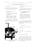
Figure 189. Top view of transmission rear housing,
showing bolts which retain brake apply cam
stationary rings
156. ASSEMBLY (figs. 377, 378, 379 and
380, fold-outs 6, 7, 8 and 9)
a . Install any plugs in transmission rear
housing 25 that were removed for cleaning
purposes .
b . If ring seal and expander were re-
moved from right-brake apply cam stationary
ring, install new replacements (fig. 191).
c . Install rightbrake apply cam station-
ary ring in the transmission rear housin g
(fig. 191).
d . If ring seal and expander were re-
moved from left-brake apply cam stationary
ring, install new replacements (fig. 190).
e . Install the left-brake apply cam sta-
tionary ring in the transmission rear housing
(fig. 190).
f . Install four 3/8-24 self-locking, bolts
with flat washers (fig. 189). Torque the bolts
to 41-49 pound-feet.
g . If bearings were removed from out-
put driven gear 49 (fig. 379, fold-out 8) in-
stall an inner bearing race assembly on each
side of the gear (fig. 188). Press the bearing
until firmly seated on the gear.
Back to Top


