TM-9-2520-234-35 - Page 168 of 323
CHAP
5,
SEC
XVIII
REAR HOUSING REBUlL D
PAR
15 6
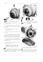
Figure 192. Installing right- and left-brake apply shafts
u . Install the right-brake apply shaft as-
sembly onto left-brake apply shaft (fig. 183).
Note . Be careful to avoid damaging
the oil seal in the right apply shaft on
the splines of the left apply shaft
(fig. 183).
v . Install the spring on the right-brake
cam assembly and position in the transmission
rear housing (fig. 192).
w . Install the right- and left-brake apply
shafts, indexing the blind splines on the shafts
with the two pins located in the right- and left-
brake cam assemblies (fig. 1 2).
x . Install brake apply shaft retainer and
gasket (fig. 181).
y . Secure with three 3/8-16 bolts an d
lock washers. Torque to 26-32 pound-feet.
z . Position the rear housing on its left
side and install 12 steel balls in the right-
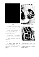
stationary cam ring (fig. 193).
aa . Install right-brake apply cam rotating
ring (fig. 193).
13 6
Figure 193. Installing right-brake apply cam rotating
ring
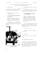
ab . Install a wood block in the rear hous-
ing, to retain the right-brake apply cam ro-
tating ring temporarily (fig. 194).
ac . Turn the rear housing over to rest
on its right side. Block the housing as neces-
Back to Top


