TM-9-2520-270-34 - Page 464 of 933
TM 9-2520-270-34
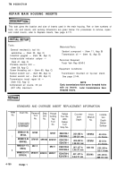
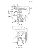
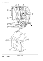
REPAIR MAIN HOUSING INSERTS
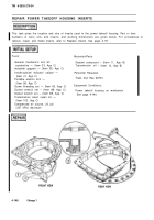
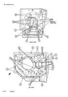
This task gives the location and size of inserts used in the main housing, Part or item numbers of
tools, kits and inserts, and working dimensions are given below. For procedures to remove, repair,
and install inserts, refer to Replace Inserts, See page 2-171.
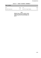
Tools:
Materials/Parts:
General mechanic’s tool kit:
Sealant compound – (Item 11, App B)
automotive — (Item 33, App C)
Transmission oil — (Item 12, App B)
Industrial goggles — (Item 39, App C)
Inside/outside indicator caliper —
Personnel Required:
(Item 41, App C)
Track Veh Rep 63H10
Portable electric drill —
(Item 58, App C)
Equipment Conditions:
Screw threading set – (Item 65, App C)
Socket wrench set – (Item 88, App C)
Transmission mounted on tip-over stand.
Socket wrench set – (Item 89, App C)
See page 2-144.
Transmission insert repair kit —
(Item 103, App C)
NOTE
Compressed air source, 30 psi
Early transmissions have some threaded holes
(207 kPa) maxirnurn
with no inserts.
Later transmissions have
threaded inserts.
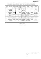
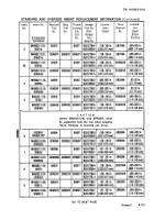
STANDARD AND OVERSIZE INSERT REPLACEMENT INFORMATION
Index
Insert No.
Removal
Step
Thread
No.
Swage
Counter-
T
OO
l
Drive
lnstalla-
Drill
Cutting
Tool No.
bore
Wrench
No.
No.
Tap
With
tion
Depth
Tool
No.
Depth
STANDARD
Swage
No.
Tool
Below
OVERSIZE
Surface
Stop No.
M45932/1-9L
SR19R
SR192L
SR19T
RZA12788-1
.082-.092 in.
SR19WA
.02-.03 in.
1
RZA12656-1
2.08-2.34 mm
.51-.76 mm
M45932/3-9L
SRW19R
SRW19D
SRW19T
RZA12789-1
SRW192L
.082-.092 in.
SR19WA
.02-.03 in.
RZA12791-1
2.08-2.34 mm
.51-.76 mm
M45932/1-17L
SR31 R
SR314L
SR31T
RZA12788-3
.097-.107 in.
SR31 WA
.035 -.045 in.
2
RZA12656-3
2.46-2.72 mm
1.02-1.14 mm
M45932/3-17L
SRW31R
SRW31D
SRW31T
RZA12789-3
SRW314L
.097 -.IO7 in.
SR31WA
.035 -.045 in.
RZA12791-3
2.46-2.72 mm
.889-1.14 mm
4-150
Change
1
Back to Top

