TM-9-2520-272-40 - Page 28 of 620
TM 9-2520-272-40
HOW TO USE THIS MANUAL – (Continued)
TROUBLESHOOTING PROCEDURES
Chapter 2 provides reference to the Field Maintenance manual, TM 9-2350-277-13&P, for
troubleshooting problems with X200-4A Transmission. No troubleshooting procedures are required
at the Sustainment Maintenance level for the X200-4A Transmission.
GENERAL MAINTENANCE INSTRUCTIONS
WP 0067, General Maintenance Information (GMI), provides general instructions which are
applicable to all areas of transmission maintenance.
Maintenance instructions in the GMI are used repeatedly throughout all of your work on the transmission.
Most of the instructions in the GMI are not repeated in the remaining maintenance work packages throughout
Chapter 3. It would be laborious for you to read through the standard cleaning and inspection steps every
time you removed something from the transmission. For that reason, certain general procedures which are
used over and over are provided only once—in the GMI. These general procedures are just as much a part
of transmission maintenance procedures as the maintenance procedures provided in the rest of Chapter 3.
The difference is that procedures in Chapter 3 are provided for you where needed. You will have to apply
procedures from WP 0067 to all tasks throughout Chapter 3 from your memory.
When procedures provided in the GMI (such as cleaning or inspection) are not adequate for a maintenance
task, then specif c instructions will be provided in the text of Chapter 4’s specif c maintenance procedures.
For example, acceptability of a part that you have removed from the transmission may depend upon
certain dimensions obtained by measurement during inspection. In such event, specif c inspection
instructions will be provided in the specif c work package in question in Chapter 3.
TRANSMISSION MAINTENANCE PROCEDURES
Maintenance procedures in Chapter 3 begin with WP 0006. The work packages proceed in logical sequence
until the transmission has been completely disassembled, repaired, and assembled.
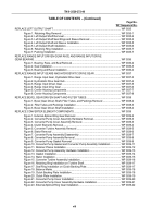
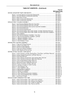
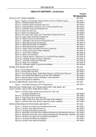
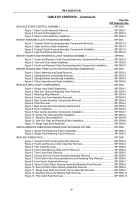
The Table of Contents will guide you to the work package for each procedure. Procedural work
packages are numbered in sequence throughout Chapter 3. A work package number and the name
of a major maintenance procedure identify each work package.
Work packages are divided into tasks. The actual maintenance work is performed from instructions at the task
level. Tasks are named and they are arranged in logical disassembly, repair, and assembly order.
TOOLS/SPECIAL TOOLS
The initial setup of each maintenance work package provides a list of common tools you will need to perform the
task. These common tools are listed by description or by tool set in which they may be found. When required, special
tools are listed by noun, along with a reference to the Tool Identif cation List in WP 0079, where manufacturer’s
code (Commercial and Government Entity Code [CAGEC]) and manufacturer’s part number can be found.
FABRICATED TOOLS
When locally manufactured, fabricated tools are required, they are listed by noun and item number and
referenced to WP 0075 of the manual, where instructions for making the tools are provided.
REPAIR PARTS
All repair parts for the X200-4A Transmission are listed in the Repair Parts and Special Tools
List (RPSTL) in a separate manual, TM 9-2520-272-40P. Mandatory replacement parts are listed
in the Materials/Parts section of the Initial Setup of each work package, when required, along
with a reference to WP 0080, where the full list can be found.
xviii
Back to Top

