TM-9-2520-272-40 - Page 18 of 620
TM 9-2520-272-40
viii
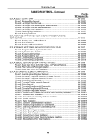
TABLE OF CONTENTS – (Continued)
Page No.
WP Sequence No.
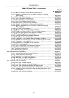
REPLACE LEFT OUTPUT SHAFT .
.................................................................................................
WP 0035
Figure 1. Retaining Ring Removal .
.....................................................................................
WP 0035-1
Figure 2. Left Output Shaft Removal .
..................................................................................
WP 0035-2
Figure 3. Left Output Shaft Seal Rings and Sleeve Removal .
............................................
WP 0035-3
Figure 4. Left Output Shaft and Sleeve Installation .
............................................................
WP 0035-5
Figure 5. Left Output Shaft Installation .
...............................................................................
WP 0035-6
Figure 6. Retaining Ring Installation .
..................................................................................
WP 0035-7
Figure 7. Packing Installation .
.............................................................................................
WP 0035-7
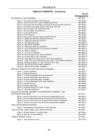
REPLACE RANGE INPUT DRIVEN GEAR RACE AND RANGE INPUT DRIVE
GEAR BEARING .
.............................................................................................................................
WP 0036
Figure 1. Bearing, Race, and Seal Removal .
......................................................................
WP 0036-2
Figure 2. Seal Installation .
...................................................................................................
WP 0036-3
Figure 3. Bearing and Race Installation .
.............................................................................
WP 0036-4
REPLACE RANGE INPUT GEARS AND HYDROSTATIC DRIVE GEAR .
.....................................
WP 0037
Figure 1. Range Input Gear, Hydrostatic Drive Gear .
.........................................................
WP 0037-3
Figure 2. Hydrostatic Drive Gear Hub .
................................................................................
WP 0037-4
Figure 3. Range Input Driven Gear .
....................................................................................
WP 0037-5
Figure 4. Range Input Drive Gear .
......................................................................................
WP 0037-6
Figure 5. Center Housing Components .
..............................................................................
WP 0037-7
Figure 6. Center Housing Components .
..............................................................................
WP 0037-8
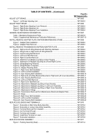
REPLACE BEVEL GEAR DRIVEN SHAFT AND FILTER TUBES .
.................................................
WP 0038
Figure 1. Bevel Gear Driven Shaft, Filter Tubes, and Packings Removal .
.........................
WP 0038-2
Figure 2. Filter Tubes and Packings Installation .
................................................................
WP 0038-3
Figure 3. Bevel Gear Driven Shaft Installation .
...................................................................
WP 0038-4
REPLACE CONVERTER ELEMENT COMPONENTS .
...................................................................
WP 0039
Figure 1. External-Splined Ring Gear Removal .
.................................................................
WP 0039-2
Figure 2. Converter Pump Cover Assembly Hardware Removal .
.......................................
WP 0039-3
Figure 3. Converter Pump Cover Assembly Removal. .
......................................................
WP 0039-3
Figure 4. Clutch Elements Removal .
...................................................................................
WP 0039-4
Figure 5. Converter Turbine Assembly Removal .
...............................................................
WP 0039-5
Figure 6. Stator Removal .
...................................................................................................
WP 0039-6
Figure 7. Converter Pump Assembly Disassembly .
............................................................
WP 0039-7
Figure 8. Converter Pump Assembly Removal .
..................................................................
WP 0039-8
Figure 9. Converter Pump Gasket Removal .
......................................................................
WP 0039-9
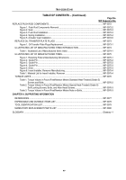
Figure 10. Converter Pump Gasket and Converter Pump Assembly Installation .
..............
WP 0039-11
Figure 11. Retainer Places Installation .
..............................................................................
WP 0039-12
Figure 12. Converter Pump Assembly Hardware Installation .
............................................
WP 0039-13
Figure 13. Gasket Installation .
.............................................................................................
WP 0039-14
Figure 14. Stator Installation .
..............................................................................................
WP 0039-15
Figure 15. Converter Turbine Assembly Installation .
..........................................................
WP 0039-16
Figure 16. Retaining Ring Installation on Turbine Shaft.
.....................................................
WP 0039-17
Figure 17. Seal Ring Installation on Clutch Backing Plate .
.................................................
WP 0039-17
Figure 18. Balance Marks .
..................................................................................................
WP 0039-18
Figure 19. Clutch Backing Plate Installation .
.......................................................................
WP 0039-18
Figure 20. Clutch Plate Installation .
.....................................................................................
WP 0039-19
Figure 21. Converter Pump Cover Installation .
...................................................................
WP 0039-20
Figure 22. Converter Pump Cover Assembly Hardware Installation .
..................................
WP 0039-21
Figure 23. External-Splined Ring Gear Installation .
............................................................
WP 0039-22
Back to Top


