TM-9-2520-272-40 - Page 17 of 620
TM 9-2520-272-40
vii
TABLE OF CONTENTS – (Continued)
Page No.
WP Sequence No.
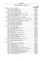
REPLACE RIGHT OUTPUT SHAFT .
...............................................................................................
WP 0028
Figure 1. Retaining Ring Removal .
......................................................................................
WP 0028-2
Figure 2. Right Output Shaft Removal .
................................................................................
WP 0028-3
Figure 3. Retaining Bearing Assembly Installation on Output Shaft .
...................................
WP 0028-4
Figure 4. Sleeve Installation .
................................................................................................
WP 0028-5
Figure 5. Right Output Shaft Installation .
.............................................................................
WP 0028-6
Figure 6. Retaining Bearing Assembly Installation .
.............................................................
WP 0028-7
REPLACE OUTER (RIGHT) STEER SHAFT, RANGE OUTPUT GEARS, STEER
SHAFT DRIVE GEAR, OUTPUT DRIVEN GEAR, AND BEARINGS .
..............................................
WP 0029
Figure 1. Outer (Right) Steer Shaft Removal .
......................................................................
WP 0029-2
Figure 2. Range Output Gears, Steer Shaft Drive Gear, and Bearings Removal .
..............
WP 0029-3
Figure 3. Bearing Inspection and Removal .
.........................................................................
WP 0029-4
Figure 4. Steer Shaft Drive Gear Installation .
......................................................................
WP 0029-5
Figure 5. Range Output Drive Gear Installation .
..................................................................
WP 0029-6
Figure 6. Range Output Driven Gear and Outer (Right) Steer Shaft Installation .
................
WP 0029-7
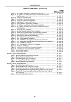
REPLACE INNER (LEFT) STEER SHAFT, RANGE OUTPUT GEAR SPACER, AND TUBES .
.....
WP 0030
Figure 1. Inner (Left) Steer Shaft and Sleeve Removal .
......................................................
WP 0030-2
Figure 2. Lube Tube and Packings and Brake Apply Tube Packing Removal .
...................
WP 0030-3
Figure 3. Brake Coolant Tube Packing and Sump Communication Tube Removal .
...........
WP 0030-4
Figure 4. Lube Tube and Packings Installation .
...................................................................
WP 0030-5
Figure 5. Brake Apply Tube, Brake Coolant Tube, and Packings Installation .
....................
WP 0030-6
Figure 6. Inner (Left) Steer Shaft and Sleeve Installation .
...................................................
WP 0030-7
REPLACE REVERSE EQUALIZER VALVE COMPONENTS .
.........................................................
WP 0031
Figure 1. Equalizer Valve Housing, Valve, and Piston Assembly Removal .
.......................
WP 0031-3
Figure 2. Equalizer Valve Diaphragm, Oil Transfer Tube, and Scavenge
Tube Assembly Removal .
.....................................................................................
WP 0031-4
Figure 3. Scavenge Tube Assembly Installation .
.................................................................
WP 0031-5
Figure 4. Oil Transfer Tube and Equalizer Valve Diaphragm Installation .
...........................
WP 0031-6
Figure 5. Equalizer Piston Assembly and Valve Installation .
...............................................
WP 0031-7
Figure 6. Equalizer Valve Housing Installation .
...................................................................
WP 0031-9
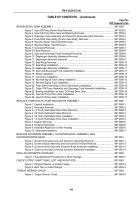
REPLACE OIL FILTER HEAD ASSEMBLY .
.....................................................................................
WP 0032
REPLACE LEFT COVER ASSEMBLY .
............................................................................................
WP 0033
Figure 1. Left Lifting Bracket Removal .
................................................................................
WP 0033-2
Figure 2. Left Cover Assembly and Gasket Removal .
.........................................................
WP 0033-3
Figure 3. Guide Pins Installation .
.........................................................................................
WP 0033-4
Figure 4. Gasket Installation .
...............................................................................................
WP 0033-5
Figure 5. Left Cover Assembly Placement on Center Housing Assembly .
..........................
WP 0033-7
Figure 6. Guide Pins Removal .
............................................................................................
WP 0033-7
Figure 7. Left Lifting Bracket Installation .
.............................................................................
WP 0033-8
Figure 8. Left Cover Assembly Installation .
.........................................................................
WP 0033-9
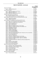
REPAIR LEFT COVER ASSEMBLY .
................................................................................................
WP 0034
Figure 1. Pipe Plugs, Inserts, and O-Rings, Left Cover Assembly Removal, View 1 .
.........
WP 0034-2
Figure 2. Pipe Plugs, Left Cover Assembly, Removal, View 2 .
...........................................
WP 0034-3
Figure 3. Pipe Plugs, Left Cover Assembly, Removal, View 3 .
...........................................
WP 0034-3
Figure 4. Insert Installer, Remover for Removal .
.................................................................
WP 0034-3
Figure 5. Pipe Plugs, Inserts, and O-Rings, Left Cover Assembly, Installation, View 1 .
.....
WP 0034-4
Figure 6. Insert Installer, Remover for Installation .
..............................................................
WP 0034-5
Figure 7. Pipe Plugs, Left Cover Assembly, Installation, View 3 .
........................................
WP 0034-5
Figure 8. Pipe Plugs, Left Cover Assembly, Installation, View 2 .
........................................
WP 0034-5
Back to Top

