TM-9-2520-272-40 - Page 13 of 620
TM 9-2520-272-40
iii
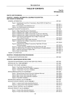
TABLE OF CONTENTS
Page No.
WP Sequence No.
HOW TO USE THIS MANUAL .
............................................................................................................
xvii
CHAPTER 1. GENERAL INFORMATION, EQUIPMENT DESCRIPTION,
AND THEORY OF OPERATION
GENERAL INFORMATION .
..............................................................................................................
WP 0001
Figure 1. Hydrokinetic Cross-Drive Transmission, Model X200-4A, Right Front
External View .
.......................................................................................................
WP 0001-1
Table 1. Nomenclature Cross-Reference List .
.....................................................................
WP 0001-4
Table 2. List of Abbreviations and Acronyms.
......................................................................
WP 0001-4
EQUIPMENT DESCRIPTION AND DATA .
.......................................................................................
WP 0002
Figure 1. Major Assemblies of the Transmission .
................................................................
WP 0002-2
Figure 2. Exploded View of Major Top Components .
..........................................................
WP 0002-3
Figure 3. Exploded View of Major Components of Left Cover Assembly .
...........................
WP 0002-4
Figure 4. Exploded View of Major Components of Right Cover Assembly .
.........................
WP 0002-5
Figure 5. Input Housing and Exploded View of Major Components
of the Torque Converter .
.......................................................................................
WP 0002-6
Figure 6. Exploded View of Bevel Gear Assembly .
.............................................................
WP 0002-7
Figure 7. Exploded View Of Major Components, Left Side Of Center
Housing Assembly .
................................................................................................
WP 0002-8
Figure 8. Exploded View Of Major Components, Right Side Of Center
Housing Assembly .
................................................................................................
WP 0002-9
Figure 9. Location and View of MWO/Overhaul Data Plate with IUID .
................................
WP 0002-10
Figure 10. External View of Container Top, Internal View of Container Bottom .
.................
WP 0002-11
Table 1. X200-4A Transmission System Data .
....................................................................
WP 0002-12
Table 2. Basic Container Data .
............................................................................................
WP 0002-13
THEORY OF OPERATION .
..............................................................................................................
WP 0003
CHAPTER 2. TROUBLESHOOTING PROCEDURES
TROUBLESHOOTINGPROCEDURES .
...........................................................................................
WP 0004
CHAPTER 3. MAINTENANCE INSTRUCTIONS
PREVENTIVE MAINTENANCE CHECKS AND SERVICES (PMCS) .
.............................................
WP 0005
REPLACE OIL FILL TUBE ASSEMBLY .
..........................................................................................
WP 0006
REPLACE TOP COVER ASSEMBLY .
..............................................................................................
WP 0007
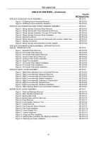
Figure 1. Top Cover Assembly Removal .
............................................................................
WP 0007-2
Figure 2. Transmission Top Cover Gasket Installation .
.......................................................
WP 0007-3
Figure 3. Transmission Top Cover Installation .
...................................................................
WP 0007-4
REPLACEMAINCONTROLVALVEASSEMBLY.
...............................................................................
WP 0008
Figure 1. Wiring Harness Ground Connector Hardware Removal .
.....................................
WP 0008-3
Figure 2. Main Control Valve Assembly Removal .
..............................................................
WP 0008-4
Figure 3. Main Control Valve Assembly Installation .
...........................................................
WP 0008-6
Figure 4. Final Bolts Installation .
..........................................................................................
WP 0008-7
REPAIR MAIN CONTROL VALVE ASSEMBLY .
..............................................................................
WP 0009
REPLACE LOCKUP CONTROL VALVE ASSEMBLY
.....................................................................
WP 0010
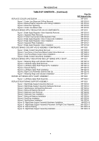
Figure 1. Lockup Control Valve Assembly Removal .
...........................................................
WP 0010-3
Figure 2. Lockup Control Valve Assembly Installation .
........................................................
WP 0010-4
REPAIR LOCKUP CONTROL VALVE ASSEMBLY .
........................................................................
WP 0011
REPLACE PRIORITY VALVE ASSEMBLY .
.....................................................................................
WP 0012
Figure 1. Priority Valve Assembly Removal .
........................................................................
WP 0012-2
Figure 2. Priority Valve Assembly Installation .
.....................................................................
WP 0012-3
Back to Top

