TM-9-2520-272-40 - Page 22 of 620
TM 9-2520-272-40
xii
TABLE OF CONTENTS – (Continued)
Page No.
WP Sequence No.
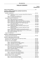
Figure 14. Bar and Stud Assembly for Retaining Ring Removal .
.......................................
WP 0056-11
Figure 15. Bar and Stud Assembly and Compressor Installed for Retaining
Ring Removal .
....................................................................................................
WP 0056-11
Figure 16. First Clutch Piston Removal .
..............................................................................
WP 0056-12
Figure 17. First Clutch Piston Seals Removal .
....................................................................
WP 0056-12
Figure 18. First Clutch Piston Seals Installation .
.................................................................
WP 0056-13
Figure 19. Seal Assembly Inserter and Remover .
..............................................................
WP 0056-13
Figure 20. Springs and First Clutch Piston Installation .
......................................................
WP 0056-14
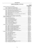
Figure 21. Bar and Stud Assembly for Retaining Ring Installation .
....................................
WP 0056-14
Figure 22. Bar and Stud Assembly and Compressor Installed for Retaining
Ring Installation .
.................................................................................................
WP 0056-15
Figure 23. First Clutch Pack Installation .
.............................................................................
WP 0056-17
Figure 24. Backing Plate and Retaining Rings Installation .
................................................
WP 0056-18
Figure 25. Range Input Shaft and Center Carrier Assembly Installation .
...........................
WP 0056-19
Figure 26. Second Clutch Piston Housing Assembly Installation .
......................................
WP 0056-20
Figure 27. Retaining Ring Selection and Installation .
.........................................................
WP 0056-21
Figure 28. Second Clutch Housing Hardware Installation.
..................................................
WP 0056-22
Figure 29. Front Carrier Assembly Installation .
...................................................................
WP 0056-23
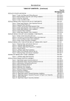
Figure 30. Third Clutch Piston Housing Assembly Hardware Installation .
..........................
WP 0056-25
Figure 31. Third Clutch Piston Housing Assembly and Retaining Ring Installation .
...........
WP 0056-25
Figure 32. Third Clutch Pack Installation .
...........................................................................
WP 0056-26
Figure 33. Third Clutch Backing Plate and Pin Installation .
................................................
WP 0056-26
Figure 34. Pitot Tubes Installation .
......................................................................................
WP 0056-27
Figure 35. Fourth and Reverse Clutch Assembly Installation .
............................................
WP 0056-27
Figure 36. Forward Clutch Housing Assembly Installation .
................................................
WP 0056-28
Table 1. Retaining Ring Selection .
......................................................................................
WP 0056-21
Table 2. Retaining Ring Selection .
......................................................................................
WP 0056-24
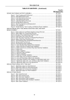
REPLACE IDLER GEAR ASSEMBLY .
............................................................................................
WP 0057
Figure 1. Bearing Retaining Plate Hardware Removal .
......................................................
WP 0057-2
Figure 2. Bearing Retaining Plate Removal .
.......................................................................
WP 0057-2
Figure 3. Hydrostatic Pump Idler Gear Removal .
...............................................................
WP 0057-3
Figure 4. Hydrostatic Pump Idler Gear Installation .
............................................................
WP 0057-4
Figure 5. Bearing Retaining Plate Installation .
....................................................................
WP 0057-4
REPLACE BEVEL GEAR ASSEMBLY .
...........................................................................................
WP 0058
Figure 1. Bevel Gear Assembly Removal .
..........................................................................
WP 0058-2
Figure 2. Bevel Gear Assembly on Wooden Supports .
.......................................................
WP 0058-3
Figure 3. Bevel Gear Assembly with Multiple-Leg Sling Attached .
.....................................
WP 0058-4
Figure 4. Bevel Gear Machined Boss Must Align with Pedestal on Center Housing .
.........
WP 0058-5
Figure 5. Pedestal On Center Housing Must Align with Machined Boss on Bevel
Gear Assembly .
....................................................................................................
WP 0058-6
Figure 6. Bevel Gear Assembly Installation .
.......................................................................
WP 0058-6
Back to Top


