TM-9-2520-272-40 - Page 14 of 620
TM 9-2520-272-40
iv
TABLE OF CONTENTS – (Continued)
Page No.
WP Sequence No.
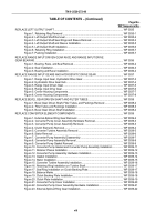
REPLACE G2 BACKUP VALVE ASSEMBLY .
.................................................................................
WP 0013
Figure 1. G2 Backup Valve Assembly Removal .
................................................................
WP 0013-2
Figure 2. G2 Backup Valve Assembly Installation .
.............................................................
WP 0013-3
REPLACE VALVE MANIFOLD MAIN WIRING HARNESS ASSEMBLY .
........................................
WP 0014
Figure 1. Wiring Harness Connector Body Removal .
.........................................................
WP 0014-2
Figure 2. Wiring Harness with Twine Attached for Removal .
..............................................
WP 0014-3
Figure 3. Wiring Harness Installation Through Oil Transfer Plate .
......................................
WP 0014-4
Figure 4. Wiring Harness Connector Body Installation .
......................................................
WP 0014-5
Figure 5. Solenoid Locations .
..............................................................................................
WP 0014-6
Figure 6. Wiring Harness Connector with Stamped Letter Location, Detail View .
..............
WP 0014-7
Figure 7. Harness Connectors .
...........................................................................................
WP 0014-7
Figure 8. Wiring Harness and Solenoids Correctly Installed .
..............................................
WP 0014-8
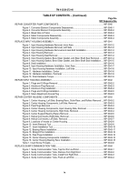
REPLACE GOVERNOR SCREEN ASSEMBLY, SEPARATOR PLATE,
AND OIL TRANSFER PLATE .
.........................................................................................................
WP 0015
Figure 1. Separator Plate Removal .
....................................................................................
WP 0015-2
Figure 2. Oil Transfer Plate Removal .
.................................................................................
WP 0015-3
Figure 3. Oil Transfer Plate Gasket Removal .
....................................................................
WP 0015-4
Figure 4. Governor Filter Screen Removal .
........................................................................
WP 0015-4
Figure 5. Governor Filter Screen Installation .
.....................................................................
WP 0015-5
Figure 6. Guide Pins Installation .
........................................................................................
WP 0015-5
Figure 7. Oil Transfer Plate Gasket Installation .
.................................................................
WP 0015-6
Figure 8. Oil Transfer Plate Installation .
..............................................................................
WP 0015-6
Figure 9. Oil Transfer Plate Bolts Installation .
.....................................................................
WP 0015-7
REPLACE RIGHT COVER ASSEMBLY .
.........................................................................................
WP 0016
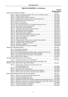
Figure 1. Right Brake Adjusting Cover and Gasket Removal .
............................................
WP 0016-2
Figure 2. Right Cover Assembly Hardware Removal .
.........................................................
WP 0016-2
Figure 3. Right Cover Assembly and Gasket Removal .
......................................................
WP 0016-5
Figure 4. Right Cover Assembly Gasket Installation .
..........................................................
WP 0016-6
Figure 5. Right Cover Assembly Lowering on Transmission .
.............................................
WP 0016-7
Figure 6. Right Cover Assembly Sling Removal .
................................................................
WP 0016-9
Figure 7. Right Cover Assembly Hardware Installation .
......................................................
WP 0016-9
Figure 8. Right Adjusting Brake Cover and Gasket Installation .
.........................................
WP 0016-0
REPAIR RIGHT COVER ASSEMBLY .
.............................................................................................
WP 0017
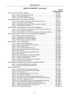
Figure 1. Seals and Bearings Removal .
..............................................................................
WP 0017-2
Figure 2. Steer Idler Bearing Removal .
...............................................................................
WP 0017-3
Figure 3. Bearing Race Slots .
.............................................................................................
WP 0017-4
Figure 4. Bearing Race and Pins Removal .
........................................................................
WP 0017-5
Figure 5. Plugs Removal .
....................................................................................................
WP 0017-7
Figure 6. Insert Installer, Remover Tool .
.............................................................................
WP 0017-8
Figure 7. Inserts Removal .
..................................................................................................
WP 0017-8
Figure 8. Pipe Plugs and Sleeve Removal .
.........................................................................
WP 0017-9
Figure 9. Pipe Plugs Installation .
.........................................................................................
WP 0017-10
Figure 10. Insert Installer Tool .
............................................................................................
WP 0017-11
Figure 11. Inserts Installation .
.............................................................................................
WP 0017-11
Figure 12. Plugs and Pins Installation .
................................................................................
WP 0017-12
Figure 13. Bearing Race and Steer Idler Bearing Installation .
............................................
WP 0017-13
Figure 14. Bearings and Seals Installation .
.........................................................................
WP 0017-15
Back to Top

