TM-9-2520-272-40 - Page 19 of 620
TM 9-2520-272-40
ix
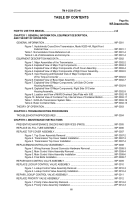
TABLE OF CONTENTS – (Continued)
Page No.
WP Sequence No.
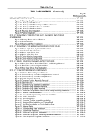
REPAIR CONVERTER PUMP COMPONENTS .
..............................................................................
WP 0040
Figure 1. Converter Element Components Disassembly .
....................................................
WP 0040-1
Figure 2. Converter Element Components Assembly .
.........................................................
WP 0040-2
Figure 3. Bleed Hole in Piston .
............................................................................................
WP 0040-2
Figure 4. Stator Components Disassembly .
........................................................................
WP 0040-3
Figure 5. Stator Components Assembly .
.............................................................................
WP 0040-4
REPLACE INPUT HOUSING ASSEMBLY .
......................................................................................
WP 0041
Figure 1. Input Housing Hardware Removal, Inner Area .
....................................................
WP 0041-2
Figure 2. Input Housing Hardware Removal, Left Side .
......................................................
WP 0041-2
Figure 3. Input Housing Hardware Removal and Jack Bolt Installation .
..............................
WP 0041-3
Figure 4. Input Housing Removal .
.......................................................................................
WP 0041-3
Figure 5. Input Housing Seal Removal .
...............................................................................
WP 0041-4
Figure 6. Input Housing Gasket, Bevel Gear Gasket, and Steer Shaft Seal Removal .
.......
WP 0041-4
Figure 7. Input Housing Gasket, Bevel Gear Gasket, and Steer Shaft Seal Installation .
.... WP 0041-5
Figure 8. Seal Installation .
...................................................................................................
WP 0041-6
Figure 9. Input Housing Hardware Installation, Inner Area .
.................................................
WP 0041-7
Figure 10. Input Housing Hardware Installation, Left Side .
.................................................
WP 0041-8
Figure 11. Hardware Installation, Center .
............................................................................
WP 0041-8
Figure 12. Hardware Installation, Perimeter .
.......................................................................
WP 0041-9
Figure 13. Final Hardware Torque .
......................................................................................
WP 0041-9
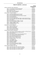
REPAIR INPUT HOUSING ASSEMBLY .
..........................................................................................
WP 0042
Figure 1. Plugs and O-Rings Removal .
...............................................................................
WP 0042-2
Figure 2. Aluminum Plug Removal .
.....................................................................................
WP 0042-3
Figure 3. Aluminum Plug Installation .
..................................................................................
WP 0042-4
Figure 4. Plugs and O-Rings Installation .
............................................................................
WP 0042-5
Figure 5. Steer Adjustment Access Plug .
............................................................................
WP 0042-5
REPAIR CENTER HOUSING COMPONENTS .
...............................................................................
WP 0043
Figure 1. Center Housing, Left Side, Bearing Race, Outer Race, and Rollers Removal .
... WP 0043-2
Figure 2. Center Housing Components, Left Side, Removal .
..............................................
WP 0043-3
Figure 3. Pipe Plugs Removal .
............................................................................................
WP 0043-3
Figure 4. Center Housing Components, Input Housing Side, Removal .
.............................
WP 0043-4
Figure 5. Center Housing Components, Right Side, Removal .
...........................................
WP 0043-4
Figure 6. Center Support Bearing Races Removal .
............................................................
WP 0043-5
Figure 7. Helical Coil Inserts, Right Side, Removal .
............................................................
WP 0043-6
Figure 8. Helical Coil Inserts, Left Side, Removal .
..............................................................
WP 0043-7
Figure 9. Locations of Inserts on Center Housing .
..............................................................
WP 0043-9
Figure 10. Insert Removal Tool .
...........................................................................................
WP 0043-9
Figure 11. Insert Installation Tool .
........................................................................................
WP 0043-10
Figure 12. Bearing Races Installation .
.................................................................................
WP 0043-11
Figure 13. Straight Pins Installation .
....................................................................................
WP 0043-12
Figure 14. Pipe Plugs Installation .
.......................................................................................
WP 0043-12
Figure 15. Center Housing Components Installation .
..........................................................
WP 0043-13
Figure 16. Center Housing Bearing Race Installation .
.........................................................
WP 0043-15
Table 1. Insert Screw Threads .
............................................................................................
WP 0043-8
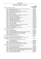
REPLACE SUMP COMMUNICATION TUBE .
..................................................................................
WP 0044
Figure 1. Sump Communication Tube, Tap Out from Left End .
..........................................
WP 0044-1
Figure 2. Sump Communication Tube, Remove from Right End .
.......................................
WP 0044-2
Figure 3. Sump Communication Tube, Install from Right End.
............................................
WP 0044-3
Figure 4. Sump Communication Tube, Flush at Left End .
...................................................
WP 0044-4
Back to Top

