TM-9-2520-272-40 - Page 359 of 620
TM 9-2520-272-40
0044
SUSTAINMENT MAINTENANCE
REPLACE SUMP COMMUNICATION TUBE
INITIAL SETUP:
Tools and Special Tools
Hammer, Hand, Soft-Face, Dead Blow, 52 oz
(WP 0079, Item 19)
Stand, Maintenance, Automotive (WP 0079, Item 40)
Tool Kit, General Mechanic’s (GMTK) (WP 0079,
Item 45)
Materials/Parts
Petrolatum, Technical (Petroleum Jelly) (WP 0078,
Item 12)
Personnel Required
Track Vehicle Repairer, 91H10
Equipment Condition
Transmission removed from vehicle or container (TM
9-2350-277-13&P)
Oil f ll tube assembly removed (WP 0006)
Input housing assembly removed (WP 0042)
REMOVE SUMP COMMUNICATION TUBE
NOTE
If sump communication tube is in position, tube does not need to be removed unless bevel
gear assembly is to be removed or tube is defective. If tube must be removed, proceed with
Steps 1, 2, and 3.
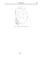
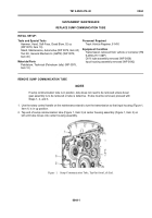
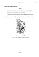
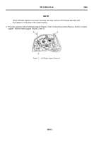
1. Use the rotary control handle on the maintenance stand to turn the transmission so that input housing (Figure 1,
Item 1) is in up position.
2. Tap end of sump communication tube (Figure 1, Item 3) at center housing assembly (Figure 1, Item 2) on
left until tube moves into center housing assembly.
Back to Top

