TM-9-2520-272-40 - Page 407 of 620
TM 9-2520-272-40
0050
SUSTAINMENT MAINTENANCE
REPLACE STEER CONTROL ASSEMBLY
INITIAL SETUP:
Tools and Special Tools
Adapter, Socket Wrench Drive, 3/8” Male x 1/2”
Female (WP 0079, Item 2)
Tool Kit, General Mechanic’s (GMTK) (WP 0079,
Item 45)
Wrench, Torque, Ratcheting, 1/2” Drive, 250 lb-ft
(WP 0079, Item 51)
Materials/Parts
Sealant, Lubricating, Thread-Locking (WP 0078,
Item 15)
Personnel Required
Track Vehicle Repairer, 91H10
Equipment Condition
Transmission removed from vehicle or container (TM
9-2350-277-13&P)
Oil f ll tube assembly removed (WP 0006)
Left steer gear, left steer and output sun gear, left
output shaft, and output pump drive gear removed
(WP 0048)
REMOVE STEER CONTROL ASSEMBLY
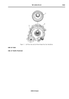
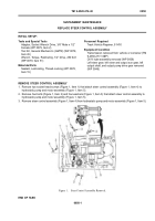
1. Remove two socket head screws (Figure 1, Item 1) that attach steer control assembly (Figure 1, Item 4) to
hydrostatic pump and motor assembly (Figure 1, Item 5).
2. Remove four bolts (Figure 1, Item 2) and four washers (Figure 1, Item 3) that attach steer control assembly to
hydrostatic pump and motor assembly (Figure 1, Item 5).
3. Remove steer control assembly (Figure 1, Item 4) from hydrostatic pump and motor assembly (Figure 1, Item 5).
Back to Top

