TM-9-2520-272-40 - Page 412 of 620
TM 9-2520-272-40
0051
REPAIR FORWARD CLUTCH HOUSING ASSEMBLY
CAUTION
When you remove, handle, or install the clutch pack, make sure that all clutch plates and
plates stay in the same order and face the same direction. Under heat and pressure, clutch
plates can take on a conical shape, called coning. The degree of coning in each plate will be
different. When coned plates are mixed or turned over, they do not install correctly together.
This can keep plate surfaces from fully engaging. If this occurs, the clutch pack to may not
operate satisfactorily.
When you replace one clutch plate or plate, replace the entire clutch pack. Do not replace only
one clutch plate because a new plate will not have the correct surface contour to engage the
adjacent older plates, This will make the operation of the clutch pack unsatisfactory.
Clutch assemblies operate in pairs. When one clutch pack is defective, a second clutch pack
will often be defective. If one clutch pack is defective, it is necessary to inspect all clutch
assemblies in the range pack.
Remove Forward Clutch Housing Assembly Components
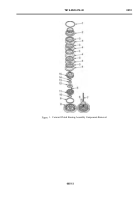
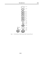
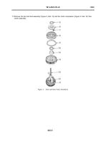
1. Remove retaining ring (Figure 1, Item 1).
2. Remove clutch assembly (hub) (Figure 1, Item 2).
3. Remove body hub (Figure 1, Item 15).
4. Remove thrust washer (Figure 1, Item 14).
5. Remove clutch pack of f ve friction plates (Figure 1, Item 3) and f ve reaction plates (Figure 1, Item 4).
6. Compress the retaining plate (Figure 1, Item 12), using wrench, bar and stud assembly (Figure 1, Item 7), and
clutch compressor (Figure 1, Item 6), to get access to the retaining ring (Figure 1, Item 13).
7. Remove retaining ring (Figure 1, Item 13).
8. Remove bar and stud assembly (Figure 1, Item 7) and clutch compressor (Figure 1, Item 6) from the housing.
9. Remove retaining plate (Figure 1, Item 12).
10.Remove 16 compression helical springs (Figure 1, Item 5).
11. Remove the piston (Figure 1, Item 11) from the clutch housing (Figure 1, Item 8).
12.Remove the inner seal (Figure 1, Item 10) and the outer seal (Figure 1, Item 9) from the piston (Figure 1, Item
11). Discard seals (Figure 1, Item 9) and (Figure 1, Item 10).
0051
‐
2
Back to Top

