TM-9-2520-272-40 - Page 408 of 620
TM 9-2520-272-40
0050
INSTALL STEER CONTROL ASSEMBLY
1. Turn transmission to input side up.
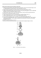
CAUTION
Before you position steer control assembly on hydrostatic pump and motor assembly,
do a check to make sure control rod pin is engaged into feedback lever. If control rod
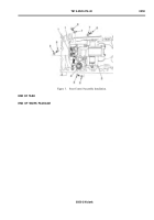
pin is not engaged into feedback lever, turn control rod until engaged. Refer to Figure 2.
Non-engagement will cause vehicle failure of full steer during start-up.
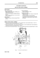
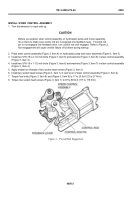
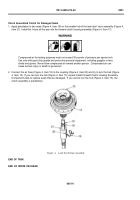
2. Place steer control assembly (Figure 3, Item 4) on hydrostatic pump and motor assembly (Figure 3, Item 5).
3. Install two 5/16-18 x 2-1/4 inch bolts (Figure 3, Item 8) and washers (Figure 3, Item 9) in steer control assembly
(Figure 3, Item 4).
4. Install two 5/16-18 x 1-1/2 inch bolts (Figure 3, Item 6) and washers (Figure 3, Item 7) in steer control assembly
(Figure 3, Item 4).
5. Apply sealant on threads of two socket head screws (Figure 3, Item 1).
6. Install two socket head screws (Figure 3, Item 1) in cam lever of steer control assembly (Figure 3, Item 4).
7
. Torquefourbo
l
ts(F
igure3
,I
tem6)and(F
igure3
,I
tem8)to17to20lb-
f
t(23to27N·m)
.
8. Torque two socket head screws (Figure 3, Item 1) to 87 to 88 lb-ft (117 to 119 N·m).
Back to Top


