TM-9-2520-272-40 - Page 466 of 620
TM 9-2520-272-40
0056
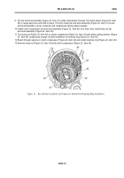
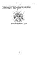
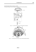
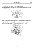
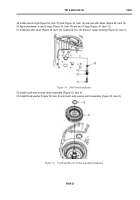
38.Use a black tube-type marker to mark edge of third clutch piston housing assembly (Figure 30, Item 21)
above bolt hole.
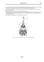
39.Install third clutch piston housing assembly (Figure 30, Item 21), aligning bolt hole in piston housing assembly
(Figure 30, Item 21) with bolt hole in center housing.
40.Install washer (Figure 30, Item 18) and bolt (Figure 30, Item 19) through center housing and into piston housing
assembly (Figure 30, Item 21) f nger tight.
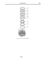
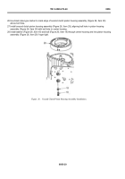
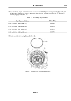
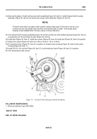
41.Use thickness gage to measure space between piston housing assembly (Figure 31, Item 21) and top of
re
ta
in
ingr
inggrooveinrangepackboreo
fcen
terhous
ing
.UseTab
le2forthese
lec
t
iono
fre
ta
in
ingr
ing
(Figure 31, Item 20).
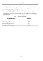
Table
2.
Retaining Ring Selection.
For Measured Distance
Select Ring
0.149 to 0.152 in. (3.79 to 3.88 mm)
6884274
0.153 to 0.155 in. (3.89 to 3.96 mm)
6884273
0.156 to 0.158 in. (3.97 to 4.03 mm)
6884275
0.159 to 0.161 in. (4.04 to 4.08 mm)
6884276
0056
‐
24
Back to Top

