TM-9-2540-207-14-P - Page 134 of 288
TM 9-2540-207-14&P
5-90
Burner Fan Plate Assembly (continued)
10.
Install Diagnostic Display (ref. 5.9.2).
11.
Attach Wiring Harness connectors for the Fuel Pressure Sensor (J4), and the Diagnostic
Display (J2).
Ensure all connectors are properly engaged.
12.
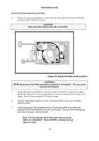
Attach the Wiring Harness connector for the Burner Fan Driver Board (J3), ensuring the
connector is properly engaged.
13.
Using a 9/16" open ended wrench, connect the fuel supply to the heater.
14.
Connect vehicle power cable to the heater MS Power connector (Control Box
Connection).
15.
Start the heater and check that there are NO fuel leaks from the fuel connections.
16.
Install Top Cover (ref. 5.4.1).
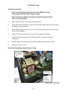
Figure 5-23. Fuel Leak Check Points
Back to Top


