TM-9-2540-207-14-P - Page 78 of 288
TM 9-2540-207-14&P
5-34
Electronic Programmed Controller & Vent Fan Driver Boards (Continued)
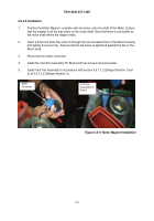
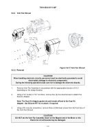
Figure 5.6-18 Detail, Screw Locations
4.
Remove the Printed Circuit Board Assembly. Using a #1 cross tip screwdriver remove
two (2) screws that hold the Vent Fan Driver Electronic Board to the Electronic
Programmed Controller Boards (ref. Figure 5.6-18 Detail, Screw Locations).
5.6.5.1.2 Installation
1.
If Vent Fan Driver Board and Electronic Programmed Controller Board have been taken
apart, apply Loctite 243 (blue) to the threads of the screws before using a #1 cross-tip
screwdriver, and fastening the Electronic Vent Fan Driver Board to the Electronic
Programmed Controller with two (2) screws.
2.
Apply Dow Corning 340 Heat Sink Compound to each of the mounting bracket surfaces
of the printed circuit board assembly.
Back to Top


