TM-9-2540-207-14-P - Page 70 of 288
TM 9-2540-207-14&P
5-26
5.6.2.2 Installation
1.
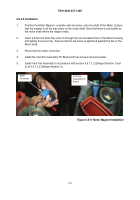
Position the Motor Magnet, complete with set-screw, onto the shaft of the Motor. Ensure
that the magnet is all the way down on the motor shaft. Note that there is a shoulder on
the motor shaft where the magnet rests.
2.
Insert a 3/32-inch Allen Key wrench through the non-threaded hole in the Motor Housing
and tighten the set-screw.
Ensure that the set-screw is tightened against the flat on the
Motor shaft.
3.
Reconnect the motor connector.
4.
Install the Vent Fan Assembly PC Board with two screws removed earlier.
5.
Install Vent Fan Assembly in accordance with section 5.6.1.1.2 (Design Iteration 1 and
2) or 5.6.1.2.2 (Design Iteration 3).
Figure 5.6-11 Motor Magnet Installation
Vent Fan
Assembly PC
Board
Motor
Connector
Back to Top


