TM-9-2540-207-14-P - Page 64 of 288
TM 9-2540-207-14&P
5-20
Vent Fan Assembly Procedure for Design Iteration 3 (Continued)
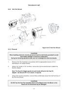
Figure 5.6-6 Vent Fan Assembly
5.
Use a 5/16" socket to remove the bolt that holds the Vent Fan to the Burner Housing.
Thread lock compound is used to secure this screw, so gentle force may be needed to
break the screw’s grip.
Figure 5.6-7
Bolt Removal Detail, Vent Fan Assembly
Take care not to damage the Combustion Air Duct during Vent Fan removal.
6.
Wiggle the Vent Fan Assembly while also pulling the Vent Fan Assembly away from the
Burner Housing Assembly.
A silicone sealant is used to seal the end of the combustion
air duct to the combustion air inlet. This seal must separated in order to remove the vent
fan assembly.
Back to Top


