TM-9-2540-207-14-P - Page 66 of 288
TM 9-2540-207-14&P
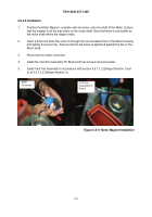
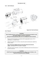
5-22
Vent Fan Assembly Design Iteration 3 (Continued)
4.
When pushing the Vent Fan Assembly onto the Burner Housing, check that the gasket
around the Burner Housing stays in position, and that the wires of the Wiring Harness
are not trapped.
Check that the Combustion Air Duct is properly mated with the Top
Housing air inlet.
5.
Tighten the bolt using a 5/16" socket. DO NOT OVER TIGHTEN.
Check that the Vent
Fan rotates freely.
6.
Attach
Wiring Harness
connector
J11
to the Electronic Programmed Controller board.
Ensure that the locking tabs are properly engaged.
7.
Attach
Wiring Harness
connector
J13
to the Electronic Programmed Controller board.
Ensure that the pins are clean and aligned properly.
8.
Install Bottom Shell (ref. 5.4.3).
9.
Install Top Shell (ref. 5.4.2).
Back to Top


