TM-9-2540-207-14-P - Page 74 of 288
TM 9-2540-207-14&P
5-30
Vent Fan Impeller Assembly (Continued)
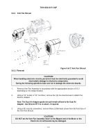
Figure 5.6-14 Detail, Vent Fan Impeller Orientation
3.
While holding the Impeller to stop it from rotating, use a 5/16" socket to remove the Vent
Fan Motor lock nut from the center of the Impeller. Inspect the lock nut and replace if
damaged.
Note: Force may be required to remove the Vent Fan Impeller. An even
prying around the rim of the base of the Vent Fan Impeller between the
Impeller and
the Vent Fan Housing may be necessary. Use caution in the
application of any such force, otherwise, the Vent Fan Housing may be
damaged.
4.
Pull Impeller from the motor shaft.
Back to Top


