TM-9-2815-200-35
ENGINE, WITH CONTAINER:TURBOSUPERCHARGED, DIESEL ,FUEL INJECTION ,90-DEGREE “V” TYPE, AIR - COOLED ,12 - CYLINDER , ASSEMBLY ;MODELS AVDS-1790-2M (2815-856-4996), AVDS-1790-2A AND AVDS-1790-2AM (2815-856-9005)
TECHNICAL MANUAL; DIRECT SUPPORT, GENERAL SUPPORT AND DEPOT MAINTENANCE MANUAL INCLUDING REPAIR PARTS AND SPECIAL TOOLS LISTS
TM-9-2815-200-35 - Page 403 of 779
Component
Front Fan
Drive
Housing
Piston
Actuated
Clutch
Assembly
Mechanical
Clutch
Assembly
Table 6-24. Front Fan Drive Housing and Clutch Assembly
Para 6-40a
Figs. 6-114
through 6-127
Para 6-40a
Figs. 6-128
through
6-130,
6-132, 6-134,
6-137 through
6-146
Para 6-40a
Figs. 6-129
through
6-131,
6-133; 6-135,
6-136, 6-138,
6-144, 6-147
Cleaning
Para 6-2
Para 6-2
Para 6-2
Inspection
Para 6-40c
Table 6-25
Para 6-40c
Table 6-26
Para 6-40c
Table 6-27
Repair
Para 6-40c
Table 6-28
Fig. 6-148
Para 6-40c
Para 6-40c
Assembly
Para 6-40d
Figs. 6-127, 6-150
through 6-152, 6-
124, 5-153, 6-122
through 6-119, 6-
154,6-155, 6-115,
6-114
Para 6-40d
Figs. 6-149,/6-146
through 6-137, 6-
134, 6-132
through 6-130, 6-
128
Para 6-40d
Figs.
6-147, 6 -
144,6-138,6-136,
6-135, 6-133, 6-
131 through 6-129
6-40. Overhaul of Front Fan Driv e
Housing and Clutch Assembly
a. Disassembly.
(1)
Front fan drive housing and cover .
Disassemble front fan drive housing and cover
following instructions which accompany figures
6-114 through 6-127.
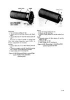
Remove
1. Cut locking wire (A).
2. Remove six drilled head bolts (B) and flat washers
attaching fan drive oil seal housing to fan drive housing
cover.
3. Install two mechanical pullers - 5120-473-7222 in
puller screw holes (C) in oil seal housing (D). Turn
screws alternately to remove housing.
Install
1. Position fan drive oil seal housing (D) on fan drive
housing cover.
2. Install six drilled head bolts (B) and flat washers
securing housing to cover.
3. Install locking wire (A) securing bolts.
Figure 6-114. Removing or installing fan
drive oil seal housing.
6-109
Back to Top


