TM-9-2815-200-35
ENGINE, WITH CONTAINER:TURBOSUPERCHARGED, DIESEL ,FUEL INJECTION ,90-DEGREE “V” TYPE, AIR - COOLED ,12 - CYLINDER , ASSEMBLY ;MODELS AVDS-1790-2M (2815-856-4996), AVDS-1790-2A AND AVDS-1790-2AM (2815-856-9005)
TECHNICAL MANUAL; DIRECT SUPPORT, GENERAL SUPPORT AND DEPOT MAINTENANCE MANUAL INCLUDING REPAIR PARTS AND SPECIAL TOOLS LISTS
TM-9-2815-200-35 - Page 394 of 779
Remove
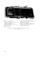
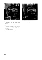
1. Remove the main oil filter stop bolt, sealing washer,
and main oil filter assembly (A).
2. Remove the auxiliary oil filter stop bolt, sealing
washer, and auxiliary oil filter assembly (B).
3. Remove and discard oil filter gaskets (C).
4. Remove eight self-locking nuts (D) and remove two
lifting eyes. Remove and discard lifting eye gasket.
Install
Note.
The lifting eye gasket is used under the
left lifting eye only.
1. Position lifting eye gasket on left side of damper and
oil filter housing. Position one lifting eye on each side of
housing and install four self-locking nuts (D) securing
each lifting eye.
2. Position a new oil filter gasket (C) on main and
auxiliary oil filter openings in housing.
3. Position the auxiliary oil filter assembly (B), sealing
washer, and auxiliary oil filter stop bolt in housing.
4. Position the main oil filter assembly (A), sealing
washer, and main oil filter stop bolt in housing.
Figure 6-102. Removing or installing main
and auxiliary oil filters.
Remove
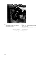
Warning:
The oil pressure regulator cover is
spring loaded. Exercise care when removing
cover.
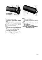
1. Remove two self-locking nuts (A) and flat washers
attaching oil pressure regulator valve cover. Remove
and discard gasket.
2. Remove oil pressure regulator valve assembly parts in
the sequence shown in figure 6-104. Note number of
flat washers (A) removed for reference during
assembly.
Install
1. Install oil pressure regulator valve assembly parts in
the sequence shown in figure 6-104. Install the same
number of flat washers (A) as removed.
2. Position a new valve cover gasket on housing. Position
valve cover on housing and install two self-locking nuts
(A) and flat washers securing cover on housing.
Figure 6-103. Removing or installing oil
pressure regulator valve cover
and gasket.
6-100
Back to Top

