TM-9-2815-205-24 - Page 158 of 856
ASSEMBLY
1.
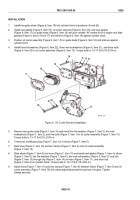
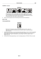
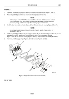
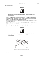
If removed, install pipe plug (Figure 5, Item 40) in bottom of oil cooler housing (Figure 5, Item 31).
2.
Place new gasket (Figure 5, Item 32) on oil cooler housing (Figure 5, Item 31).
NOTE
Inlet opening is marked "FROM" on cover and "IN" on oil cooler. Outlet opening is marked
"TO" on cover and "OUT" on oil cooler. Oil coolers must be installed in correct position to
prevent any foreign particles and sludge from entering engine or transmission.
3.
Carefully place transmission oil cooler (Figure 5, Item 33) inside oil cooler housing (Figure 5, Item 31).
NOTE
Do not install bolts in locations (Figure 5, Item A), (Figure 5, Item B), (Figure 5, Item C),
and (Figure 5, Item D).
4.
Install new gasket (Figure 5, Item 34), cover (Figure 5, Item 36), six flat washers (Figure 5, Item 39), six new
lockwashers (Figure 5, Item 38), and six bolts (Figure 5, Item 37) on transmission oil cooler
(Figure 5, Item 33) and oil cooler housing (Figure 5, Item 31). Torque bolts to 13–17 lb-ft (18–23 N·m).
5.
If removed, install four pipe plugs (Figure 5, Item 35) in cover (Figure 5, Item 36).
31
A
B
D
C
32
33
35
36
37
38
39
35
34
40
MAINT_060
Figure 5.
Engine/Transmission Oil Cooler Assembly.
END OF TASK
TM 9-2815-205-24
0021
0021-8
Back to Top

