TM-9-2815-205-24 - Page 152 of 856
REMOVAL
1.
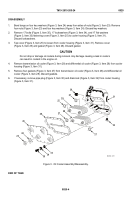
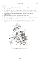
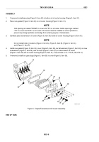
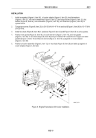
Loosen two hose clamps (Figure 1, Item 7) and slide hose (Figure 1, Item 6) down onto oil cooler assembly
(Figure 1, Item 12).
2.
Remove two bolts (Figure 1, Item 1) through clip (Figure 1, Item 3), two lockwashers (Figure 1, Item 2),
elbow (Figure 1, Item 4), and gasket (Figure 1, Item 5) from cylinder block. Discard gasket and lockwashers.
If necessary, remove clip (Figure 1, Item 3) from air box heater fuel line.
3.
Remove hose (Figure 1, Item 6) and two clamps (Figure 1, Item 7) from oil cooler assembly
(Figure 1, Item 12).
4.
If necessary, remove pipe plug (Figure 1, Item 17) from elbow (Figure 1, Item 4).
5.
Remove two short bolts (Figure 1, Item 11), four long bolts (Figure 1, Item 16), six lockwashers
(Figure 1, Item 10), and six flat washers (Figure 1, Item 9) from oil cooler assembly (Figure 1, Item 12) and
clip (Figure 1, Item 8). Discard lockwashers.
6.
Remove four nuts (Figure 1, Item 15), four lockwashers (Figure 1, Item 14), and four flat washers
(Figure 1, Item 13) from oil cooler assembly (Figure 1, Item 12). Discard lockwashers.
1
2
3
4
5
6
7
8
9
10
11
12
13
14
15
16
10
9
17
MAINT_056
Figure 1.
Engine/Transmission Hardware Removal.
TM 9-2815-205-24
0021
0021-2
Back to Top

