TM-9-2815-205-24 - Page 353 of 856
INSTALLATION - Continued
1
36
34
35
MAINT_462
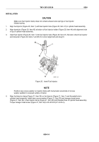
Figure 21.
Install Fuel Injector Clamp.
5.
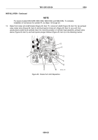
Slide end of injector control lever (Figure 22, Item 37) into socket at end of fuel injector control rack
(Figure 22, Item 40). By hand, loosely tighten control lever adjusting screw (Figure 22, Item 38) on injector
control tube (Figure 22, Item 39) just enough to keep ball-end of injector control lever (Figure 22, Item 37)
snug in socket at end of fuel injector control rack (Figure 22, Item 40).
37
38
39
40
MAINT_463
Figure 22.
Connect Fuel Injector Rack.
TM 9-2815-205-24
0054
0054-15
Back to Top


