TM-9-2815-205-24 - Page 352 of 856
INSTALLATION
CAUTION
Make sure fuel injector clamp does not contact exhaust valve springs or fuel injector
follower spring.
1.
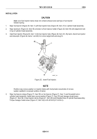
Align fuel injector (Figure 20, Item 1) with fuel injector tube (Figure 20, Item 41) in cylinder head assembly.
2.
Align dowel pin (Figure 20, Item 45) at bottom of fuel injector holder (Figure 20, Item 44) with alignment hole
in top of cylinder head assembly.
3.
Insert fuel injector (Figure 20, Item 1) into fuel injector tube (Figure 20, Item 41). By hand, check fuel injector
and dowel pin (Figure 20, Items 1 and 45) for correct alignment and snug fit.
44
45
41
1
MAINT_461
Figure 20.
Insert Fuel Injector.
NOTE
Position new convex washer on injector clamp with hump-back curved side of convex
washer saddled in recessed surface of clamp.
4.
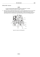
Align fuel injector clamp (Figure 21, Item 36) on fuel injector (Figure 21, Item 1) and threaded hole in
cylinder head assembly. Install new convex washer (Figure 21, Item 35) and hexagon head screw
(Figure 21, Item 34) in fuel injector clamp (Figure 21, Item 36) and threaded hole of cylinder head assembly.
Torque hexagon head screw (Figure 21, Item 34) to 20–25 lb-ft (27–34 N·m).
TM 9-2815-205-24
0054
0054-14
Back to Top


