TM-9-2815-205-24 - Page 354 of 856
INSTALLATION - Continued
NOTE
Throughout the installation steps, refer to placement references and information
that was marked and tagged to parts during removal steps.
For engine models 5063-5299, 5063-5392, 5063-5393, and 5063-539L: To
complete installation of fuel injectors for all cylinders, except #1 on right cylinder
head assembly, do Steps 6 through 12 and 22 through 24.
Mounting/use of eye brackets will vary from one cylinder location to another.
(1)
For cylinder #1 (left cylinder head assembly, only), an eye bracket will be
mounted on the rear rocker arm shaft bracket.
(2)
For cylinder #2, an eye bracket will be mounted on both the front and rear
rocker arm shaft brackets.
(3)
For cylinder #3, an eye bracket will be mounted on the front rocker arm
shaft bracket.
Steps 6 through 12, which follow, pertain to the two eye brackets mounted on the
two rocker arm shaft brackets at cylinder #2. Adjust task step procedures as
required, for installation of single eye brackets at other cylinders.
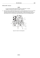
6.
Raise two machine bolts (Figure 23, Items 27 and 33), front rocker arm shaft bracket (Figure 23, Item 26),
rear rocker arm shaft bracket (Figure 23, Item 34), two eye brackets (Figure 23, Items 23 and 30), rocker
arm shaft (Figure 23, Item 28), two exhaust valve rocker arms (Figure 23, Item 2), and fuel injector rocker
arm (Figure 23, Item 3), as a unit, from upside-down position and carefully lower into mounting position on
cylinder head assembly, exhaust valve stems (Figure 23, Item 5) and fuel injector plunger follower
(Figure 23, Item 4) in the following manner:
27
23
26
4
5
28
3
2
33
30
34
28
MAINT_464
Figure 23.
Cylinder #2 Rocker Arm Unit Reposition.
TM 9-2815-205-24
0054
0054-16
Back to Top


