TM-9-2815-220-24 - Page 373 of 1563
TM 9-2815-220-24
WIRING HARNESS AND CABLE REPAIR
0056 00
REPLACEMENT OF CONNECTORS (Continued)
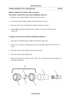
Disassembly of Heat Shrink Insulation Tubing
1.
Cut, remove, and discard old insulation tubing.
Assembly of Heat Shrink Insulation Tubing
NOTE
Insulation tubing should be twice the diameter of the part over which
it will be shrunk.
1. Slide heat shrink insulating tubing (item 35, 36, WP 0173) over wire and terminal.
NOTE
Remove thermal heat gun from tube as soon as tube forms to shape of
wire and terminal.
2. Hold electric heat gun (item 63, WP 0176) 4 or 5 inches (101.6 - 127.0 mm) away from tubing
and apply heat for about 30 seconds.
3. Let tube cool 30 seconds before handling.
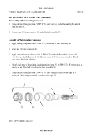
Disassembly of Wire Contacts
1. Cut and discard contacts.
2. Strip about 1/2 inch (12.7 mm) of insulation from end of the wire.
Assembly of Wire Contacts
NOTE
Color bands on contacts indicate wire size.
For example, contacts
with green color bands are for 22-gauge to 26-gauge wire.
Contacts
with red color bands are for 20-gauge to 24-gauge wire.
1. Place contacts in the crimping tool with the color band toward the rear.
2. Place bare wire in the contact and squeeze the crimping tool.
3.
Remove crimped contact out of the tool and check the crimp by looking in the inspection hole.
Verify that the end of the bare wire is visible.
Disassembly of Crimped Terminal
C
B
A
1. Cut and discard terminal (A).
Assembly of Crimped Terminal
1. Strip cable electrical insulation sleeving
equal to depth of terminal (A) well.
2. Push cable (B) against end of terminal (A) well and crimp.
3. Apply a dab of silicone sealant (item 33, WP 0173) to exposed end of wire (C).
WP 0056 00-13
Back to Top

