TM-9-2815-220-34 - Page 114 of 532
TM 9-2815±²20³34
capscrews and lockwashers (4). CoNnect spring
(3)
To I±jectIoN pump leveR a±d to aNgle bracket² ³N-
sTalL manual fuel shUtoff Rod ´2) and secuRe To I±µ
jecTIo± pUmp leVer with FlaT washers and cotTeR pIN
±1².
(8.1)
rnstaU a
n
g
l
e
brcket (5,
fig. 241±1² on
Fuel
iNjecTioN pump ANd sec±Re wiTh tl²-ee
lock-
washerS and CapSCRewS
±4).
CoNNect
throTtle
cON³
T´Ol RoD a
s
e
m
b
L
y
³7´ To
pUmp
Lever aND SeCUµe
wItH mAChine bolT, OaT waSheµ a¶D seLF·loCk¸ng
±U
(6).
¹TTaCH The FµonT eºD oF T»e ThrotTle CoNT¼ol
ro½ asseMBly ¾7¿
tO tHe iNTeµMe¶iate TH·ottle JeveR
aNd
Se
c
U
r
E
wiTH
¸achiNe bOlt,
¹ºt
WASHE· ¸¹nd
se
l
f
ºL
O
Ck
»
N
g
ºÀT
Á8².
ÂÃÃaCh
t
h
e
mA±UA¼
½uEl
sh±T»OF¼ ½od asSembly (2¾ to ¿he sÀ±tÁOf leveR aNd
seCure
witÀ ÃaÄ washeÅ aN¶ cotte´
pIn ¾¿ÀÁ ÂnÃT¸J¿
MaN±al ƱeL sÀuTÇOFf leVeµ ÈetÉÊ spRING (3¾Ë
Ì9Í
Pos»TIoN FUeL »Nject»o± pUmp coUplINg
sLeeves makINg sUre t»ming maÄks on beaÄing ReÅ
taiNiNg pLaTe and coupLing hub remain alinedÆ
Çhese marks musT be ali±ed beFore atTempTINg to
assemble The couplI±gÈ Éoosely posIÊIoN fOuR lock
plates, lock washeRs, a±d machINe bolTs ËÌgÍ 2ºÎ3Ï iN
dRIVe shafT coUplInG sleeÐesÑ PosITIo± Two 5/16Ò»nÓ
sTeeL rods ´ÌgÔ
2-54²,
i± sleeVe aLIneme±T holesÕ Öold
fUel Inje×TIon ØUmp dÄIve coupl»Ùg sleeve ´±eaResT
the pump) sTaTionarY a±d ÄoTaÚe The oTheÄ dRive
couplINg sleeve counteÄcLockwIse To remove
backlash from The pUmp driVe shaftÛ Ühen
backLash Is removed, a±d FLat sIdes of drive coUÝ
pliNgs are aLIned, tighteN ÞUr dßive couplI±g boLts
secuàelYá âãen fLat sIdes oF däåVe couplIng sleeves
æçègÕ 2éêëÀ do ±oT maTe whe± backlash Is remoVedì
The coupling sLeeVes mUsT be separaTed a±d ÄeseTí
îepaïðaTe coUpñ»ng a±d push sleeVe of dR»Ðe shafT
FÄom hub spl»±esÑ òdjusT sLeeVe o± spl»nes so óaT
sIdes oF coupLIng halves are aliNedá ôoRque TIghTen
couplI±g boLts To õ7ö To
3³5
poundº»±chesÍ ÷emoVe
Two p»pe pluGs Ëøùgú
³´5µ²
ûüom coupl»±gsá
(10¶ InstalL ·/16´³7
lUbricatIo± FItTi±g and Luý
brIcate coupLing þÿTh
MI¸¹G´813³³
GreaseĀ DIscoNµ
Tinue adding LUbāåcaTion when gRease shows I± The
hole o± opposITe side of coupli±gÕ Ăver fIlLINg caVITY
wiăl
ĄESąlĆ
»n
failεe
oF
co±PliNG sealsÏ ÐeMove
lubÑÒcatioN FÓttiNG ÔÕÖt×ll the Pipe Pl±GS
ć½ĈĉĊ ċºČč)Ď
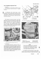
ďĐđĒ ēnsTaĔĕ ThÄoTTle cRoss ĖhafT ėĘackeT
(´,
FęgĚ
³¹5º»,
end plaTe ´6Ï a±d ThRoTTlě lInkage Us»±g ±ew
gaskeT aT Ĝ÷ cYlindeRĚ ĝnsTall one Ğapscrew a±<ğ
lockwasheÄ ´Î) seĠUÄ»ng e±d plaTe To the cyl»nġer
aNd two capsĞrews aNd lockwasheßs
µ7)
secUrINg
ThRotTLe cRoss shaFt brackeT to ĢLampeÄ housingÛ
PositioN pRImarY fuel filTeÄ aNd brackeT
¼5
aNd
InsTall Two capscrews a±d loģk washeÄs
½3².
PosiTIon
thÄoTtle co±tRoL rod and levĤÄ and I±sTall selfĥ
loĦk»nħ ±UT anĨ machĩne bolT ´Đ)Ñ ĪosęTīo± ma±uaĬ
¶·¸6
C
h
a
º
g±
¹
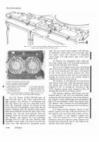
F'igul±eI-54. Rt1²³0L´µ1¶G/·(¸¹ i¶ºjU»µo¼¶½¾¶¿ÀÁp drµÂ•E gÃaÄ TÅAÆn
bNckÇÈsÉÊË
fÌÍyζ¾ÏÐÑÒÓÔ ÕÖ ×Ø CÙÚ Í Û¶J¶ÜÝÞ;ß,චἶ²¼¶Îá¼âã¶äå
t'P
æçOèΜéê ¶ëY wìíh
lubd
îÈïið¼ñ
fiL²
ͼò{󵼶ôõíö÷øùúûü
fUeL shuĭºO½F rod a±d leVĮr aNd »nsTall óat washer
and cotter pi±
¾³¿À
¾Á³)
įheİk throtTle co±Tıo¼ adIJusTabLe rod æFigÕ
³Â56²,
ma±ual FUel shuTéoff Rod and ThÄoTTle operaTij
Ing Lever rod ½or ûĴee moVemenTĚ
Á13´
[±SĵĶlL
check
Vķlvĸ
Ø6Ù
f¸gÄ 2ÅÆ0DZ
c
o
n
-
I
Nect f±el ReT±Ú hose (5¾ TO cÛeÜk ValVE Ý6¾Ù aN
±el
ÞNLet
hose
Ø
²³
aN
Oil
iÕLet
hose
(ß¾ TO
aDaPTeRsà CONNeáT electRical lea¶ (âãË
´Ĺĺ) Ü»Th ThroTTle lInkage
¸º
full ThĘoTTLe posIµ
T»on (Ļ, F»gĀ 2ºö7), cleaàaNce beTwee± leveR stop pI±
a
N
D sTop on
bµacket ¸äSt bå æ/16
i
Nç
h MI±imUļú
Üi¶h
ThµoTTLe ÈInkage
i± ĽdLĸ p
Oè
I
t
i
o
n
ºB»¼ ½
l
ea
r
A
n
¾
e
Bľ¶wĿľ± LeVľR
stop pIN éN¶ StOp ON b½aêkë¿ ¸±St
be ßìí6
Inch mIn»mUmŀ
WîeN ÄÀï foµðgoiNñ còe×µó
aNcôs aõe öot Met÷ lOøùeN lo K N±tè ON ú¶ûüStaBlý
µo¶ Øþã, ÿND a¶Ā±sā
ROà 㥠NąçĆsćĈµY
Tĉ ObĊċČN
Back to Top


