TM-9-2815-224-34-P - Page 198 of 554
TM9-2815-224-34&P
Valve Mechanism Maintenance Instructions (Cont)
7-9. CAMSHAFT REMOVAL/REPAIR/lNSTALLATION.
This task covers:
a. Removal
d. Assembly
b. Disassembly
e. Installation
c. Cleaning/Inspection
f. Follow-on Maintenance
INITIAL SETUP
Models
References
All
None
Test Equipment
Equipment Condition
None
Special Tools
Puller, camshaft gear J1902-01
Remover, camshaft gear and water pump
pulley J7932
Set, dial indicator J7872
Gage, feeler FB310B
Supplies
Solvent, dry cleaning, Item 60, Appendix C
Oil, lubricating, Item 48, Appendix C
Grease, automotive and artillery, Item 36,
Appendix C
Tags, identification, Item 61, Appendix C
TM or Para
Condition Description
TM 9-2320-279-34 Engine installed on engine
stand.
Para 3-7
Cylinder heads removed.
Para 5-3
Flywheel housing and rear
oil seal removed.
Para 7-12
Front balance cover
removed.
Para 10-5
Water pump drive gear
removed.
Special Environmental Conditions
None
General Safety Instructions
Personnel Required
None
MOS 63W, Wheel vehicle repairer
Level
of Maintenance
General Support
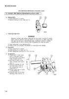
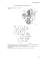
a. Removal.
(1)
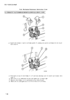
Remove four screws (l), adapter (2), and
retainer (3) from left camshaft gear (4).
7-20
Back to Top

