TM-9-2815-225-34-P - Page 293 of 736
TM 9-2815-225-34&P
0031 00
0031 00-9
AIR COMPRESSOR (Contd)
ASSEMBLY (Contd)
15.
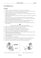
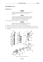
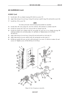
Install plate (18) on cylinder housing (19) with two screws (17).
16.
Apply lubricating oil to new large O-ring (35) and new small O-ring (33) and install on seat (34).
17.
Install disc (32) on seat (34).
NOTE
Use shim previously removed during disassembly for assembly.
18.
Install shim (30), new spring (31), seat (34), with disc (32) attached, in cylinder head (9).
19.
Install new spring (36), valve (37), and seat (38) in cylinder head (9).
20.
Install new gasket (10), cylinder head (9), new gasket (8), and cover (7) on cylinder housing (19)
with four washers (6), new lockwashers (5), and bolts (4). Tighten bolts (4) 15–19 lb-ft
(20–26 N
•
m).
21.
Apply lubricating oil to new large O-ring (42) and and install on valve body (1).
22.
Apply lubricating oil to new small O-ring (41) and install on valve body (1).
23.
Install new spring (39), new cap (40), and valve body (1) on cover (7) with two washers (2) and
screws (3). Tighten screws (3) 96–132 lb-in (11–15 N
•
m).
Figure 10. Air Compressor Assembly.
31
33
42
41
39
35
1
2
3
30
36
32
34
37
38
10
9
9
7
6
5
4
40
13
12
12
11
21
24
26
28
25
23
27
29
22
20
19
16
15
14
18
17
Back to Top


