TM-9-2815-225-34-P - Page 286 of 736
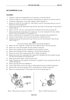
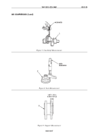
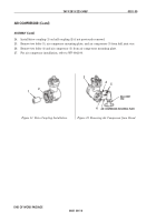
Figure 1. Mounting Air Compressor on Stand.
Figure 2. Half Coupling Removal.
TM 9-2815-225-34&P
0031 00
0031 00-2
AIR COMPRESSOR (Contd)
DISASSEMBLY
1.
Install air compressor mounting plate on air compressor (1) with two bolts (2).
2.
Install air compressor (1) and air compressor mounting plate on ball joint vise with two bolts (3).
3.
Using half coupling puller, remove half coupling (4) from crankshaft (5).
4.
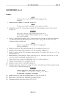
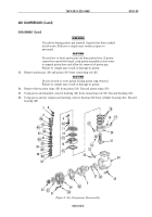
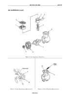
Remove two screws (8), two washers (7), valve body (6), cap (44), and spring (43) from cover (12).
Discard cap (44) and spring (43).
5.
Remove large O-ring (46) and small O-ring (45) from valve body (6). Discard large O-ring (46) and
small O-ring (45).
6.
Remove seat (42), valve (41), and spring (40) from cylinder head (14). Discard spring (40).
7.
Remove four bolts (9), lockwashers (10), washers (11), cover (12), and gasket (13) from cylinder
head (14). Discard lockwashers (10) and gasket (13).
8.
Remove cylinder head (14) and gasket (15) from cylinder housing (24). Discard gasket (15).
9.
Using press and mandrel, remove seat (38) from bottom of cylinder head (14).
10.
Remove large O-ring (39) and small O-ring (37) from seat (38). Discard large O-ring (39) and
small O-ring (37).
NOTE
Do not discard shim. Shim will be reused during installation.
11.
Remove disc (36), spring (35), and shim (34) from cylinder head (14). Discard spring (35).
12.
Remove two screws (22) and plate (23) from cylinder housing (24).
13.
Remove drive coupling (33) from crankshaft (5) if not previously removed.
14.
Remove thrust bearing (32) from crankshaft (5). Discard thrust bearing (32).
15.
Remove two screws (25) securing support (29) to cylinder housing (24).
16.
Remove four screws (31), lockwashers (30), support (29), and gasket (28) from cylinder housing
(24). Discard lockwashers (30) and gasket (28).
17.
Rotate piston (20) 90° before or after top dead center.
18.
Rotate crankshaft (5) while pulling out and remove crankshaft (5) from connecting rod (21) and
cylinder housing (24).
19.
Remove pipe plug (27) from crankshaft (5).
20.
Using a ridge reamer, remove any ridge or carbon deposits from top of cylinder housing (24).
21.
Remove piston (20) and connecting rod (21) out through top of cylinder housing (24).
22.
Remove two retaining rings (17) from piston (20). Discard retaining rings (17).
1
2
4
5
3
2
AIR COMPRESSOR
MOUNTING PLATE
BALL JOINT
VISE
Back to Top

