TM-9-2815-225-34-P - Page 282 of 736
TM 9-2815-225-34&P
0030 00
0030 00-4
ENGINE RETARDER (Contd)
ASSEMBLY
NOTE
Lubricate all parts with OE/HDO 10 lubricating oil before
assembly.
1.
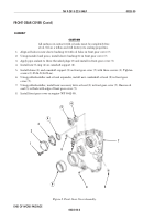
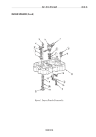
Install electrical terminal (14) in brake housing (13).
NOTE
Perform steps 2 and 3 to install two slave piston assemblies.
2.
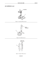
Install slave piston (19), new slave piston spring (20), and slave piston retainer (21) in brake
housing (13).
WARNING
Slave piston spring is highly compressed. Be extremely
careful during assembly. Personal injury can occur if spring
force is not controlled.
3.
Using a C-clamp and deep-welled socket, compress slave piston spring (20) and install retaining
ring (22) in brake housing (13). Slowly release slave piston spring (20) pressure and remove
C-clamp and deep-welled socket.
NOTE
Setscrews and locknuts will be tightened during engine
retarder installation.
4.
Install two setscrews (12) in brake housing (13). Do not tighten setscrews (12).
5.
Install two new locknuts (11) on setscrews (12). Do not tighten locknuts (11).
6.
Install two master pistons (18), new master piston springs (15), washers (16), and screws (17) in
brake housing (13).
7.
Apply OE/HDO 10 lubricating oil on new upper seal ring (8), new center seal ring (9), and new
lower seal ring (10), and install on solenoid valve (6).
8.
Using solenoid valve wrench, install solenoid valve (6) in brake housing (13).
9.
Connect electrical harness (7) to solenoid valve (6).
10.
Install two control valves (1) in brake housing (13).
11.
Install two new inner control valve springs (3) and two new outer control valve springs (2) on top
of control valve (1) in brake housing (13).
WARNING
Control valve cover is under control valve outer spring
pressure. Hold cover securely when installing screws. Failure
to comply may cause injury to personnel.
12.
Install control valve cover (4) on brake housing (13) with two screws (5).
13.
Repeat steps 1 through 12 for remaining two engine retarders.
14.
For engine retarder installation, refer to WP 0043 00.
Back to Top

