TM-9-2815-225-34-P - Page 288 of 736
TM 9-2815-225-34&P
0031 00
0031 00-4
AIR COMPRESSOR (Contd)
CLEANING AND INSPECTION
1.
For general parts cleaning information, refer to CLEANING, WP 0051 00.
2.
For general parts inspection information, refer to INSPECTION, WP 0051 00.
CAUTION
Cylinder head top surface is contoured. Do not grind or
machine cylinder head. Failure to do so will cause cylinder
head leakage and damage to air compressor.
NOTE
Replace any part that does not pass visual inspection or is
outside specified wear limits.
3.
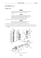
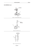
Inspect cylinder head (1) and cover (2) mating surfaces for scratches, scoring, cracks and pitting.
4.
Inspect drive coupling (9) for chipped or stripped teeth, and cracks.
5.
Inspect support (8) for cracks, scratches, and scores.
6.
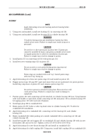
Inspect connecting rod (5) inside diameters for scratches, scoring and cracks.
7.
Using straight edge and feeler gauge, measure connecting rod (5) for bend and twist. Discard
connecting rod (5) if bend is greater than 0.002 in. (0.508 mm) maximum, and twist maximum is
greater than 0.004 in. (0.102 mm).
8.
Using inside micrometer, measure connecting rod (5) crankshaft end inside diameter. Maximum
diameter is 1.935 in. (49.149 mm). Discard connecting rod (5) if maximum diameter is exceeded.
9.
Inspect cylinder housing (6) for scratches, scoring, and cracks.
10.
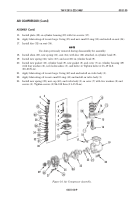
Using a line bore gauge, measure cylinder housing (6) bore inside diameter and bore out-of-round
dimensions. Maximum cylinder housing (6) inside bore diameter allowed is 3.6285 in. (9.2164 cm).
Maximum cylinder housing (6) bore out-of-round dimension allowed is 0.0015 in. (0.0381 mm).
Discard cylinder housing (6) if either measurement is over limit.
11.
Hone bore of cylinder housing (6) to remove glaze.
12.
Inspect piston (3) for scoring, pitting, chips, or cracks.
13.
Using inside micrometer, measure piston pin (3) bore. Replace piston (3) if piston pin bore is
above 0.6885 in. (17.4879 mm).
14.
Using micrometer or equivalent, measure piston pin (4) outside diameter. Replace piston pin (4) if
outside diameter is above 0.6876 in. (17.4625 mm).
15.
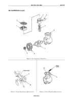
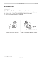
Position a new piston ring (11) in piston ring groove (10). Using a feeler gauge, check the
clearance between piston ring (11) and piston ring groove (10). Discard piston (9) if clearance is
more than 0.004 in. (0.1016 mm).
16.
Position a new piston ring (11) in top of cylinder housing (6) bore. Using a feeler gauge, measure
piston ring (11) end gap. Piston ring (11) gap must be between 0.010–0.020 in. (0.254–0.508 mm).
If correct gap cannot be obtained, replace piston ring (11).
Back to Top


