TM-9-2815-225-34-P - Page 292 of 736
TM 9-2815-225-34&P
0031 00
0031 00-8
AIR COMPRESSOR (Contd)
ASSEMBLY
NOTE
Apply lubricating oil on new bushing and new bearing before
installation.
1.
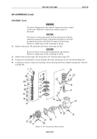
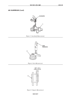
Using press and mandrel, install new bushing (11) in connecting rod (16).
2.
Using press and mandrel, install new bearing (21) in cylinder housing (19).
WARNING
Use gloves during piston pin installation if piston has been
soaked in hot water. Failure to comply may result in injury to
personnel.
CAUTION
Do not force or drive piston pin in piston bore. If piston pin
cannot be installed by hand, soak piston assembly in hot water
to expand piston bore to allow for installation of piston pin.
Failure to comply may result in damage to piston.
3.
Install piston (15) on connecting rod (16) with piston pin (14).
4.
Install two new retaining rings (12) in piston (15).
CAUTION
Do not scratch or score piston during piston ring removal.
Failure to comply may result in damage to piston.
NOTE
Piston rings are marked with word “top”. Install piston rings
with word “top” facing up.
5.
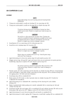
Apply lubricating oil to three new piston rings (13) and install on piston (15).
6.
Stagger piston rings (13) gap 180° apart and ensure they are not positioned over piston pin bore.
Install ring compressor on piston (15) and compress piston rings (13).
CAUTION
Do not force piston in cylinder housing bore. Excessive force will
crack piston rings. Failure to comply may result in damage to
equipment.
7.
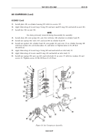
Position piston (15) with connecting rod (16) attached, in cylinder housing (19) bore. Using hammer
with wood handle or equivalent, install connecting rod (16) and piston (15) in cylinder housing (19)
by tapping piston (15) with wood end of hammer.
8.
Install pipe plug (22) in crankshaft (23).
9.
Rotate piston (15) 90° before or after top dead center in cylinder housing (19). To allow for
crankshaft (23) installation.
10.
Apply lubricating oil to crankshaft (23), connecting rod (16), bearing (21), and cylinder
housing (19).
11.
Rotate crankshaft (23) while pushing in to install crankshaft (23) in connecting rod (16) and
cylinder housing (19).
12.
Install new gasket (24) and support (25) on crankshaft (23) and cylinder housing (19) with six new
lockwashers (26) and screws (27). Tighten screws (27) 30–35 lb-ft (41–47 N
•
m).
13.
Apply lubricating oil to new thrust bearing (28) and install on crankshaft (23).
14.
Apply lubricating oil to half coupling (29). Using press, install half coupling (29) on crankshaft (23).
Back to Top

