TM-9-2910-226-34 - Page 39 of 208
TM 9-2910-226-34
d.
plus
At any position of equilibrium the spring load
the servo pressure is equal to regulator
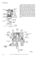
pressure. The diaphragm (fig. 1-28) or piston (fig. 1-
29) is connected by linkage to a wedge-shaped
movable block which serves to vary the position of
the full-load cam in the injection pump.
Proper
selection of the full-load stop wedge angle and servo
diaphragm or piston spring rate produces the
amount of compensation required to maintain
constant power output over a range of fuels.
e.
These fuel density compensators are man-
ufactured to provide the fuel compensation for the
multifuel engines. Each fuel injection pump must be
constructed for the particular engine for which it is
designed.
f.
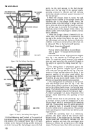
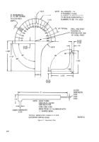
Code G injection pumps are not equipped with
a fuel density compensator. They have a stationary
stop plate and bridge assembly attached to the
governor housing (fig. 1-30). The stop plate and
bridge assembly accomplishes the same function as
the compensator stop plate except it does not
compensate for various viscosity fuels.
1-28.
Fuel Injection Pump Data.
Manufacturer .
Model . . . . . . . . . . . . . . . . . . . . . . . . .
.. . . . . . . . . . . . . . . . . .
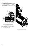
Figure 1-30. Stop plate and bridge assembly (code G).
American Bosch Division
PSB-6A
Length. . . . . . . . . . . . . . . . . . . . . . . . . . . . . . . . . . . . . .
17.75 in. (approx)
Width.
. . . . . . . . . . . . . . . . . . . . . . . . . . . . . . . . . . . . . . . . 6.50 in. (approx)
Height:
2910-178-1185 (code A). . . . . . . . . . . . . . . . . . . . . . . . . . . . . . . . .11.50 in. (approx)
2910 -759 -5419 (code Canal D). . . . . . . . . . . . . . . .
. . . . . . . . . . . . . . . . . . . . . 11.50in. (approx)
2910 -103 -2644 (code E)
. . . . . . .
. . . . . . . . . . .
. . . . . . . . . . . . . . . . . . . . . . . . . . .11.50 in. (approx)
2910-017-9778 (early code F). . . . . . . . . . . . . . . . . . . . . . . . . . . . . . .
. . .12.87 in. (approx)
2910-908-6320 (code Band late code F) . . . . . . . . . . . . . . . . . . . . . . . . 11.50in. (approx)
2910-860-2333 (early code G) . . . . . . . . . . . . . . . 9.7in. (approx)
2910-968-6317 (late code G). . . . . . . . . . . . . . . . . . .
9.7 in. (approx)
Name plate location. . . . . . . . . . . . . . . . . . . . . . . . . . . . . . .
Top left side of governor housing
Mounting data:
Number of mounting holes
3
. . . . . . . . . . . . . . . . . . . . . . . . . . . . . . . . . . .
Diameter mounting holes . . . . . . . . . . . . . . . . . . . . . . . 0.406
Governor speed range (on DF-1 fuel):
Idle
Full
load
(code
A)
.
.
.
.
.
.
.
.
.
.
.
.
.
.
.
.
650-700
2800
2910-759-5410 (code C and D) . . . . . . . . . . . . . . . . . . . . . . . . 650-700 2600
2910-103-2644 (code E)
. . . . . . . . . . . . . . . . . . . . . . . . . . . . . . 650-700 2600
2910-017-9778 (early code F) . . . . . . . . . . . . . . . . . . . . . . . . . . . 650-700 2600
2910-908-6320 (code Band late code’ F) . . . . . . . . . . . . . . . . . . . . . . .
650-700 2600
(early
code
G).
.
.
.
.
.
.
.
.
.
.
.
.
550-600
2800
2910-968 -6317 (late code G) . . . . . . . . . . . . . . . . . . . . . . . . . . . . 550-600
2800
Rotation (viewed from drive end) . . . . . . . . . . . . . . . . . . . . . . . . .Clockwise
Fuel injection sequence. . . . . . . . . . . . . . . . . . . . . . . . . . . . . . .1, 5, 3, 6, 2, 4
Delivery valve opening pressure . . . . . . . . . . . . . . . . . . . .250-400 psi
Overflow pressure. . . . . . . . . . . . . . . . . . . . 5 psi max.
Fuel pressures, minimum (after final filter):
700 RPM . . . . . . . . . . . . . . . . . . . . . . . . . . . . . . . . . . 30 psi min.
2600 RPM
60 psi min.
. . . . . . . . . . . . . . . . . . . . . . . . . . . . .
Fuel density compensate (all except 2910-860-2333 and 2910-968-6317 pumps):
Pressure regulator valve setting (all fuels) . . . . . . . . . . . . . . . . . . . . . . . . .20-21 psi
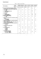
1-29. Differences Between Injector Pumps.
Table 1-
the item in the description column is used on that
1 lists the major differences between the pumps used
particular pump.
on the various engines. An X in the column indicates
1-31
Back to Top

