TM-9-2920-257-30-P - Page 29 of 111
TM 9-2920-257-30&P
(a)
Positive diodes -
[1]
Set ohmmeter to X100 scale and make sure ohmmeter is zeroed.
Connect one lead of the
multimeter to pin B or C of the output connector.
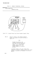
Connect the other lead to each of the six heat sink phase terminals S
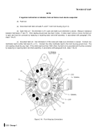
(fig.
2-15).
All six readings should be nearly alike; either less than 600 ohms or very high.
If all six readings are not alike,
the diode rectifier assembly is defective.
Replace heat sink assembly or front housing assembly, in accordance with
paragraph 3-4b, steps 1 thru 17.
[2]
Reverse phase leads, and observe resistance between pin B or C of the output connector and each
of the six heat sink terminals S (fig.
2-15).
All six readings should be nearly alike, but opposite the readings obtained
previously; if all readings were less than 600 ohms before, all readings should be very high now and vice versa.
If any
readings is not alike, the diode rectifier is defective, replace heat sink assembly, in accordance with paragraph 3-4b, steps
1 thru 17.
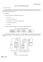
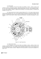
Figure 2-15.
Diode Testing Points
(b)
Negative Positive diodes -
[1]
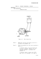
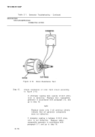
Set ohmmeter to X100 scale and make sure ohmmeter is zeroed.
Connect one lead of the
multimeter to the ground terminal on the outside of the front housing and connect the other lead to each of the six heat
sink phase terminals S (fig. 2-15).
All six readings should be nearly alike and read very high.
If all six readings are not
alike, the diode rectifier assembly is defective.
Replace the front housing assembly, in accordance with paragraph 3-4b,
steps 1 thru 17.
2-22
Change 1
Back to Top

