TM-9-2920-257-30-P - Page 26 of 111
TM 9-2920-257-30&P
d.
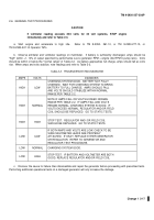
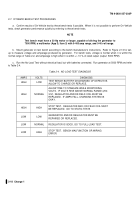
Run the full-load Test at 5000 RPM.
Increase load to the rated output +/- 10% and refer to Table 2-5.
Table 2-5.
FULL-LOAD TEST DIAGNOSIS
AMPS
VOLTS
DIAGNOSIS
HIGH
LOW
TEST BENCH BATTERY DISCHARGED OF DEFECTIVE.
ALLOW TO CHARGE OR REPLACE.
HIGH
NORMAL
CHARGING SYSTEM OKAY.
HIGH
HIGH
STOP TEST.
REGULATOR AND /OR FIELD COIL MUST
BE REPLACED.
GO TO STATIC TESTS.
LOW
LOW
GENERATOR AND/OR REGULATOR MUST BE
REPAIRED OR REPLACED.
LOW
NORMAL
INCREASE LOAD
LOW
HIGH
STOP TEST.
BENCH MALFUNCTION OR WIRING
ERROR.
2-8.
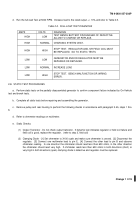
STATIC TEST PROCEDURES
a.
Perform static tests on the partially disassembled generator to confirm component failure indicated by On-Vehicle
test and bench tests.
b.
Complete all static tests before repairing and assembling the generator.
c.
Remove pulley and rear housing to perform the following checks in accordance with paragraph 3-4b, steps 1 thru
6.
d.
Refer to ohmmeter readings on multimeter.
e.
Static Checks:
(1)
Output Transistor - Do not check output transistor.
If dynamic test indicates regulator or field coil failure and
field coil is good, replace the regulator.
(refer to step 3, field coil)
(2)
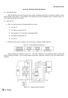
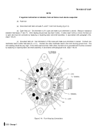
Clamping Diode - [1] Set ohmmeter to X100 scale and make sure ohmmeter is zeroed.
[2] Disconnect the
regulator.
[3] Connect one multimeter lead to pin E.
[4] Connect the other lead to pin B and observe
ohmmeter reading.
In one direction the ohmmeter should read less than 600 ohms, in the other direction
the ohmmeter should read very high.
If ohmmeter reads less than 600 ohms in both directions (short) or
very high in both directions (open) clamping diode is defective and regulator must be replaced.
Change 1
2-19
Back to Top

